3
FI002K0018v1100UK – THS/21 Instruction manual for installation, use and maintenance
INSTALLATION
50 ORIGINAL INSTRUCTIONS
3.1.2.2.3 Models THS/G21 and THS/G21E
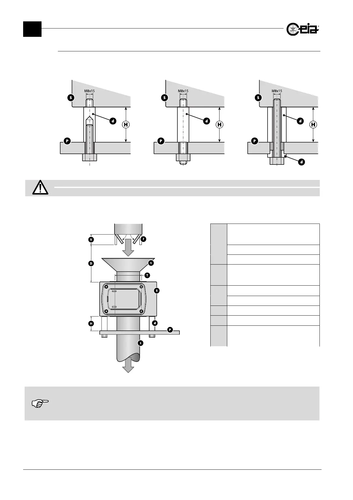
Insert the Metal Detector antenna on the material inspection pipe. Fix it in position using the screws
and plastic spacers as shown in the figures below; use the holes on the lower side of the antenna
(see section 2.7.1).
S: Detector probe; P: Support frame; d: Plastic spacer
Fix the probe cable to the power supply unit so that it cannot oscillate or vibrate.
If the cable is too long, DO NOT CUT THE CABLE: COIL UP THE EXCESS.
The distance between the probe and fixed or moving masses depends on the sensitivity selected
and on the size of the masses. The figure below shows the typical distances:
H
Distance between probe S and
support plate P
H 0.5 T
d
Rigid plastic spacer
f
Steel moving part
D
Distance between probe S and
the moving part f
D 1.5 T
P
Stainless steel support plate
S
Probe
T
Diameter of the probe
t
Plastic material
V
Moving part reference
dimension
V = 200x160x2 mm
The distances given are intended as a guide only and refer to a sensitivity setting of 280 and default settings.
The actual distances depend on the model and dimensions of the Metal Detector, the settings for the current product and
the metal mass involved.
It is the customer’s responsibility to ensure that the Metal Detector is really compatible with the application and the static
and moving metal parts.