16-30
Software Configuration Guide—Release IOS XE 3.6.0E and IOS 15.2(2)E
OL_28731-01
Chapter 16 Configuring VLANs, VTP, and VMPS
VLAN Membership Policy Server
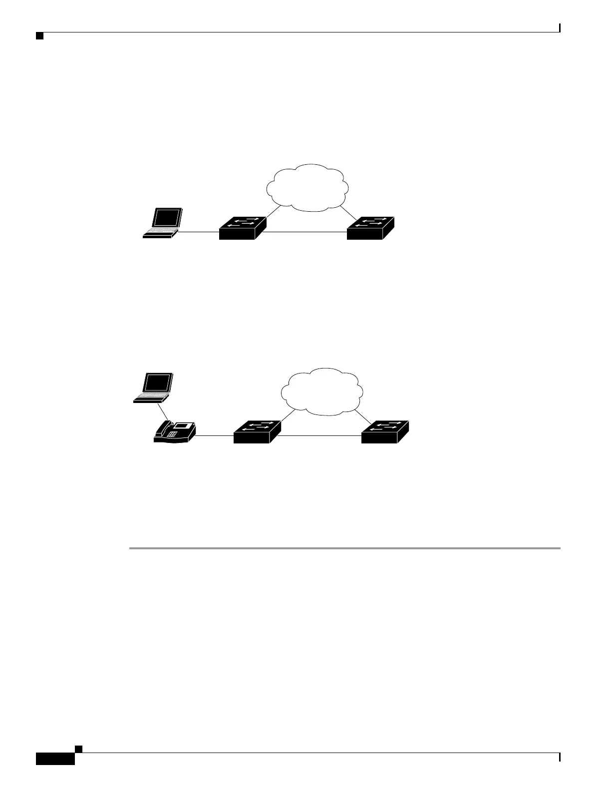
Two topologies are possible. Figure 16-5 illustrates a topology with one end station attached directly to
a Catalyst 4500 series switch operating as a VMPS client. Figure 16-6 illustrates a topology with an end
station attached to a Cisco IP Phone, which is attached to a Catalyst 4500 series switch.
Figure 16-5 Topology with an End Station Attached Directly to a Catalyst 4500 Series Switch
Operating as a VMPS Client
Figure 16-6 Topology with an End Station Attached to a Cisco IP Phone that is Attached to a
Catalyst 4500 Series Switch
In the following procedure, the Catalyst 4500 and Catalyst 6500 series switches (running Catalyst
Operating System) are the VMPS servers. Use this procedure to configure the Catalyst 4500 series
switch clients in the network:
Step 1 Configure the VMPS server addresses on Switch 2, the client switch.
a. Starting from privileged EXEC mode, enter global configuration mode:
switch# configuration terminal
b. Enter the primary VMPS server IP address:
switch(config)# vmps server 172.20.26.150 primary
c. Enter the secondary VMPS server IP addresses:
switch(config)# vmps server 172.20.26.152
d. To verify your entry of the VMPS IP addresses, return to privileged EXEC mode:
switch(config)# exit
Endstation
(in VLAN 10)
Catalyst 4500 (IOS)
(VMPS client)
Catalyst 4500 (CatOS)/
Catalyst 6500 (CatOS)/
URT
(VMPS server)
130118
Internet
Cisco IP phone
(in VLAN 10)
Endstation
(in VLAN 20)
Catalyst 4500 (IOS)
(VMPS client)
Catalyst 4500 (CatOS)/
Catalyst 6500 (CatOS)/
URT
(VMPS server)
130119
IP
Internet

 Loading...


