SLM-5650B Satellite Modem
Revision 2
Appendix A A–2 MN-SLM-5650B
A.2.1 Interface Checkout
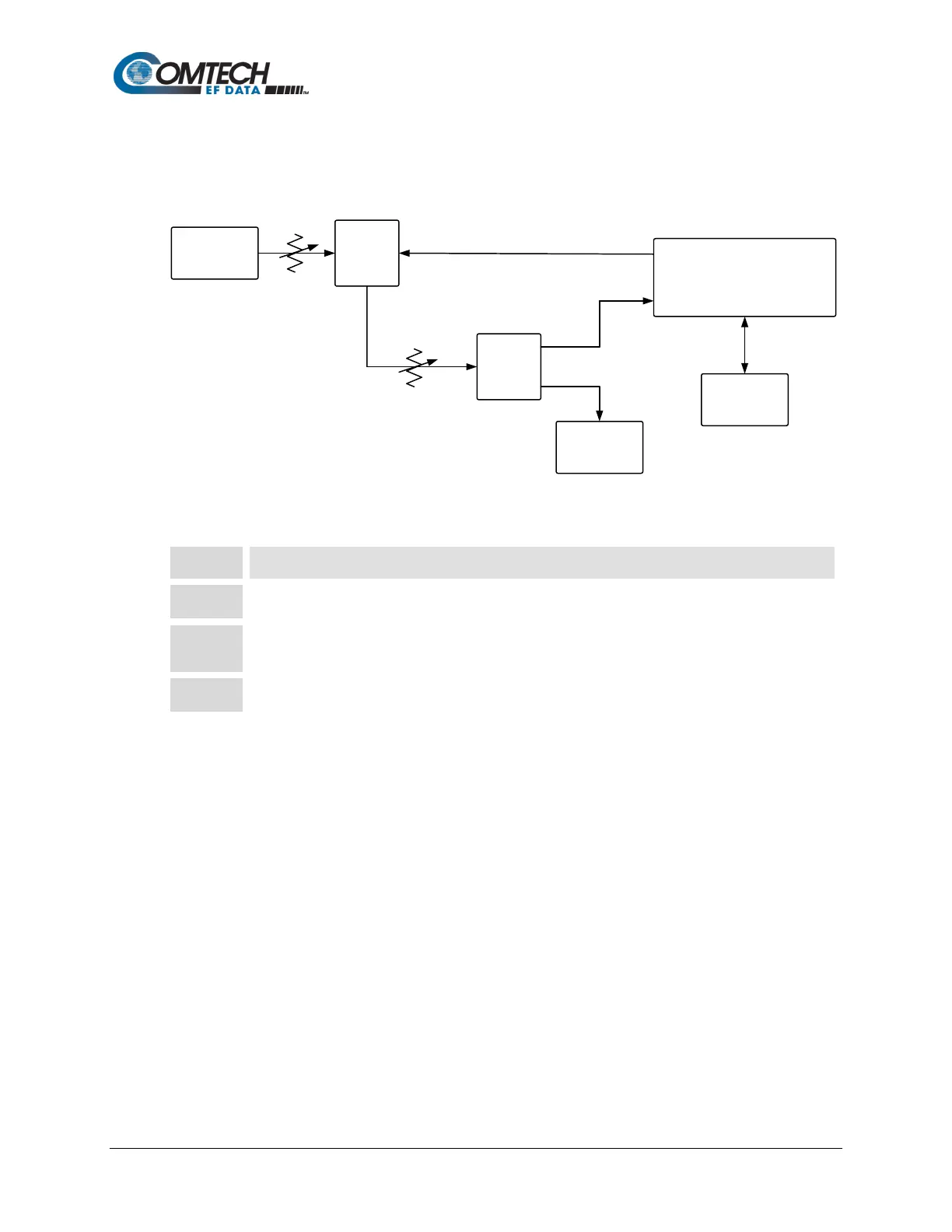
Use the test setup in Figure A-1 and the procedure that follows to verify the Ethernet interface.
Noise
Generator
Spectrum
Analyzer
Packet
Generator
Modem Under Test
TX
Rx
Splitter
Splitter
Variable
Attenuator
Variable
Attenuator
Figure A-1. Fault Isolation Test Setup
Step Task
Ensure the correct IF interface is selected and configured for the proper mode of operation.
Connect a packet generator test set to the appropriate Ethernet traffic data connector as shown in
Figure A-1.
Set up the packet generator for the desired rate, packet size, etc. The modem will run error-free.