SLM-5650B Satellite Modem
Revision 2
Rear Panel Connectors and Pinouts 3–2 MN-SLM-5650B
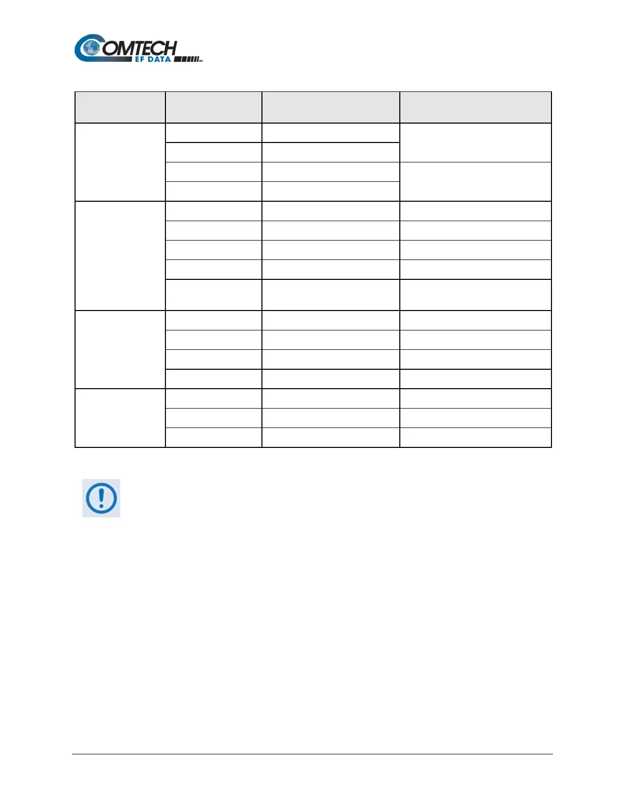
Table 3-1. SLM-5650B Rear Panel Connectors
(Chapter Sect.)
Ref Des / Name Connector Type Function
(Sect. 3.2)
IF Output
J11 Tx TNC female (70/140MHz band)
J4 Rx Type ’N’ female (L-Band)
IF Input
J3 Rx TNC female (70/140MHz band)
Terrestrial Data
(Sect. 3.3)
J5 Ethernet RJ-45 female 10/100Base-T, Remote Control
P1 Overhead Data 25-pin Type ‘D’ male
2
See Sect. 3.3.2 for details
J6 EIA-530 25-pin Type ‘D’ female
2
Data I/O to 20 Mbps
(Interface Option Slot)
See Sect. 3.3.5 Supports optional data interfaces
Utility
(Sect. 3.4)
J1 Ext Ref TNC female Modem Reference I/O
J8 Alarms 9-pin Type ‘D’ female
2
Form C Alarms (relay closures)
2
See Sect. 3.4.3 for details
2
Serial Remote Interface (RS232/485)
(Sect 3.5)
AC See Sect. 3.5.1 Chassis power
DC N/A Chassis power
Ground #10-32 stud Common Chassis Ground
To maintain compliance with the European EMC Directive 2004/108/EEC (EN 55022,
EN-55024), properly shielded cables are required for all data I/O.
The ‘D-Shell’ connectors (J6, J8, J9, J10, P1) provided on the SLM-5650B rear panel
feature threaded nuts to ensure the mechanical integrity of the mated connections.