SLM-5650B Satellite Modem
Revision 2
Appendix E E–2 MN-SLM-5650B
E.2 SLM-5650B Processing Flow and Symbol Rate Calculation
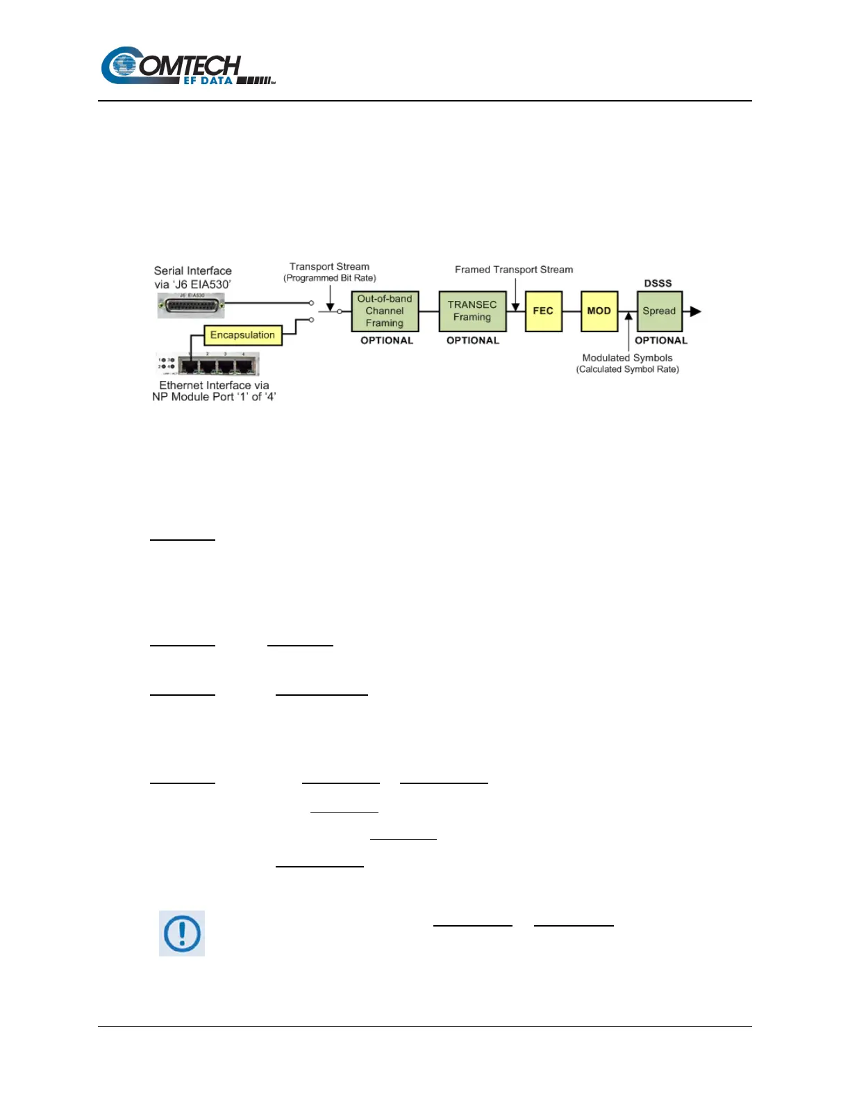
The SLM-5650B supports both serial and Ethernet interfaces, and provides options for framing,
modulation and spreading. Figure E-1 shows the processing flow for these functions when the
SLM-5650B ‘J6 EIA530’ rear panel connector and the optional Network Processor Module’s Port
‘1’ are used for the Serial and Ethernet interfaces, respectively.
Figure E-1. SLM-5650B – Feature Block Diagram
The symbol rate S
R
(Carrier 3dB Bandwidth) is a function of the programmed data bit rate B
R
with FEC encoding, modulation, and transport overhead factors as shown in the equation
“
S
R
=B
R
/M
O
C
R
F
RS
F
T
F
C
”
(referred to hereafter as “Equation 1”), containing the following
Operands:
• Operand 1 – M
O
= Modulation Order ‘1’ if BPSK
‘2’ if QPSK
‘3’ if 8PSK
‘4’ if 16QAM
• Operand 2 – C
R
= Code Rate of the Forward Error Correction (FEC) (e.g., CR = 0.75 if stated
FEC code rate = “3/4”)
• Operand 3 – F
RS
= Reed Solomon Framing Factor, where:
o F
RS
= (n/k) where (201,219) is default RS for MIL-165A
o
F
RS
= 1 where the RS is disabled.
• Operand 4 – F
c
= CnC AUPC Mode or ACPC Control Framing Factor, where:
o F
C
= 15/16 if AUPC Mode is enabled;
o F
C
= 32605/32768 if ACPC Mode is enabled;
o F
C
= 1 if neither feature is enabled.
Only one of these two features (AUPC Mode or ACPC Mode) may be enabled
at any given time.