SLM-5650B Satellite Modem
Revision 2
Rear Panel Connectors and Pinouts 3–9 MN-SLM-5650B
3.4 Utility Connectors
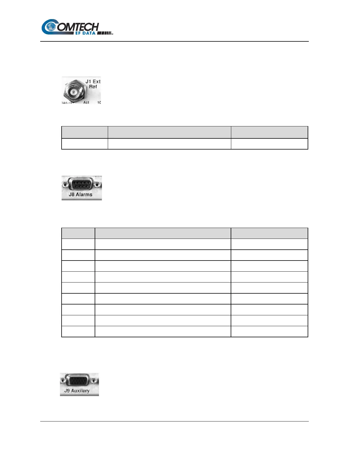
3.4.1 J1 Ext Ref (External Reference) (Type ‘TNC’)
The J1 External Reference uses a standard 50 Ω TNC female connector:
Table 3-7. J1 External Reference (Type ‘TNC’)
Ref Des / Name Description Direction
External Reference 1, 5, 10 MHZ
3.4.2 J8 Alarms Connector (DB-9F)
This is a female Type ‘D’ 9-pin (DB-9F) connector that provides Form C contact
closures for alarm reporting. The three Form C summary fault contacts are
Modulator, Demodulator, and Common Equipment.
Table 3-8. J8 Alarms Connector (DB-9F) Pinout
1 Unit Alarm common COM
6 Unit Alarm is not faulted NO
2 Unit Alarm is faulted NC
4 Rx Alarm common COM
3.4.3 J9 Auxiliary Connector (HD-15F)
This is a female type ‘HD’ 15-pin (HD-15F) connector that provides TTL open
collector faults for the modulator and demodulator; a TTL input for external
transmit carrier mute; an Analog demodulator Q and I constellation monitor; and a
programmable DC voltage monitor for the demodulators AGC.