SLM-5650B Satellite Modem
Revision 2
Appendix A A–14 MN-SLM-5650B
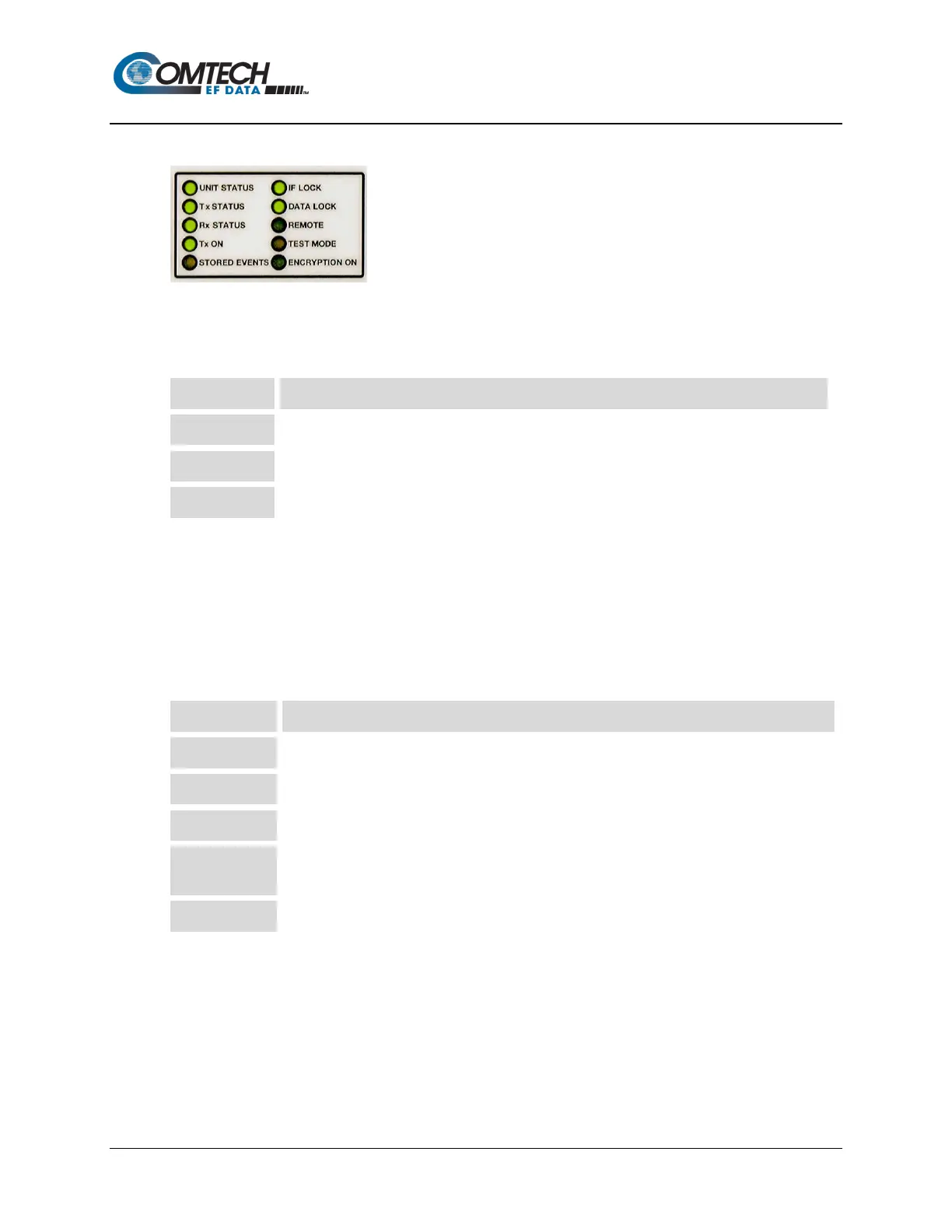
A.5 LED Display and Description
The ten LEDs located on the modem’s front panel indicate status, fault, and alarm information.
GREEN indicates no faults or alarms currently exist.
ORANGE ORANGE indicates an alarm currently exists. It is stored in the Event Log memory.
RED indicates a fault currently exists. It is stored in the Event Log memory.
A total of 255 occurrences of any fault can be stored. Each fault or stored fault indicated by a
front panel LED could be one of many faults. Use the Fault or Stored Fault front panel menu to
determine which fault has occurred.
Alarms are considered minor faults. Alarms are shown in the Fault or Stored Fault front panel
menu by a reversed-contrast “+” that appears at the display panel (white on black).
LED Description
Modulator output status. If illuminated, output is turned on.
Demodulator Carrier Detect. If illuminated, the carrier is locked
DATA LOCK Decoder Data lock. If illuminated, the decoder is locked.
REMOTE
Modem remote control status. If the LED is green, the modem is in remote control; if off, the
modem is in local control.
Modem test mode indicator. If illuminated, a test mode is enabled.