Nano Series GigE Vision Camera Connecting the Genie Nano Camera • 95
Connectors
The Nano has two connectors:
• A single RJ45 Ethernet connector for control and video data transmitted to/from the host
computer Gigabit NIC. The Genie Nano also supports Power over Ethernet (PoE).
See Ruggedized RJ45 Ethernet Cables for secure cables.
• A 10 pin I/O connector for camera power, plus trigger, strobe and general I/O signals. The
connector supports a retention latch, while the Nano case supports thumbscrews. Teledyne
DALSA provides optional cables (see Optional Cable Accessories). See 10-pin I/O Connector
Pinout Details for connector pin out specifications.
• Note that the NanoXL uses the same two connectors but on a larger camera body.
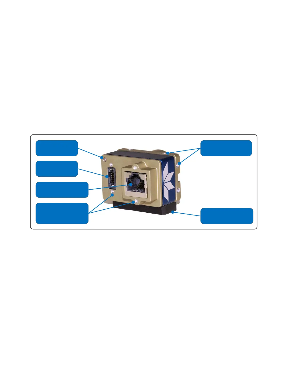
The following figure of the Genie Nano back end shows connector and LED locations. See
Mechanical Specifications for details on the connectors and camera mounting dimensions, including
the NanoXL.
Status LED
10 Pin
I/O & Power
Ethernet Connector
(supports PoE)
Supports
Thumbscrew
Secured Cables
Camera Mounts
(4 sides)
Optional Tripod
Mount
Genie Nano – Rear View

 Loading...


