250 • Technical Specifications Nano Series GigE Vision Camera
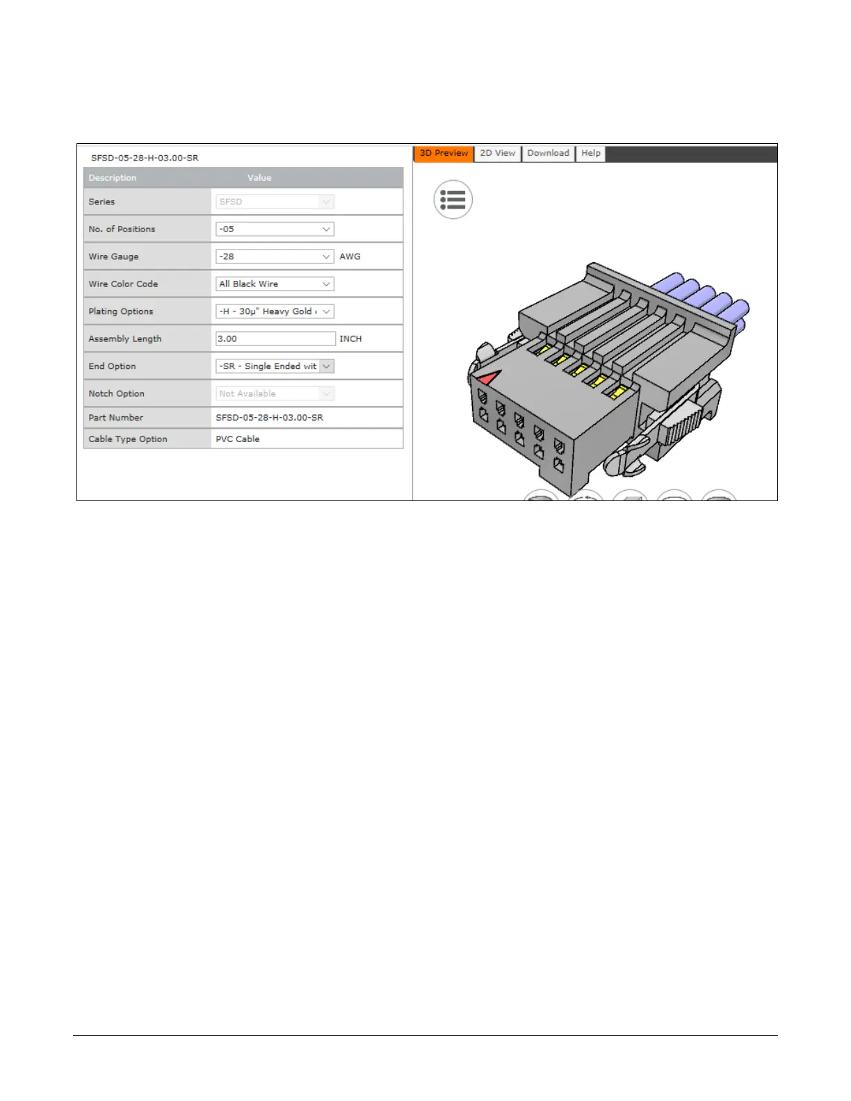
Samtec connector-cable assembly SFSD-05-28-H-03.00-SR w/retention clips
“.050” Tiger Eye™ Double Row Discrete Wire Cable Assembly, Socket”
Power over Ethernet (PoE) Support
• The Genie Nano requires a PoE Class 0 or Class 2 (or greater) power source for the network
if not using a separate external power source connected to pins 1 & 2 of the camera’s I/O
Connector.
• To use PoE, the camera network setup requires a powered computer NIC supporting PoE, or
a PoE capable Ethernet switch, or an Ethernet power injector.
• Important: Connect power via the I/O connector or PoE, but not both. Although Nano has
protection, differences in ground levels may cause operational issues or electrical faults.
• If both supplies are connected and active, the Nano will use the I/O power supply
connector. But as stated, ground differences may cause camera faults or failure.
• Important: When using PoE, the camera’s I/O pin 1 (Camera Power – Ground) must not be
connected to I/O pin 3 (General Input Common Ground).
Note: Serial port models do not support PoE camera power, therefore they must use external
power connected via the I/O connector. This avoids grounding issues between PoE sources and the
serial port UART.
“G3-GM4… or G3-GC4…” part numbers denote optional “Serial Port” special order models.

 Loading...


