192 • Operational Reference Nano Series GigE Vision Camera
Important Usage Details
• Two to 16 ROI areas are supported by the Genie Nano (4x4 matrix maximum).
• For any selected ROI, the Offset X/Offset Y features define the upper left corner of the ROI.
• Offset, Width, and Height features have individual increment values (step size) to consider.
• The first ROI of any row sets the “height value” for any other ROI in that row.
• The first ROI of any column sets the “width value” of any other ROI in that column.
• Note that the Nano firmware by default provides a 4x4 sample multi-ROI setup for easy
verification of this function.
The following graphics show examples of the multi-ROI function (2x1 and 2x2 areas), the resultant
camera output and the constraints when configuring the ROI areas.
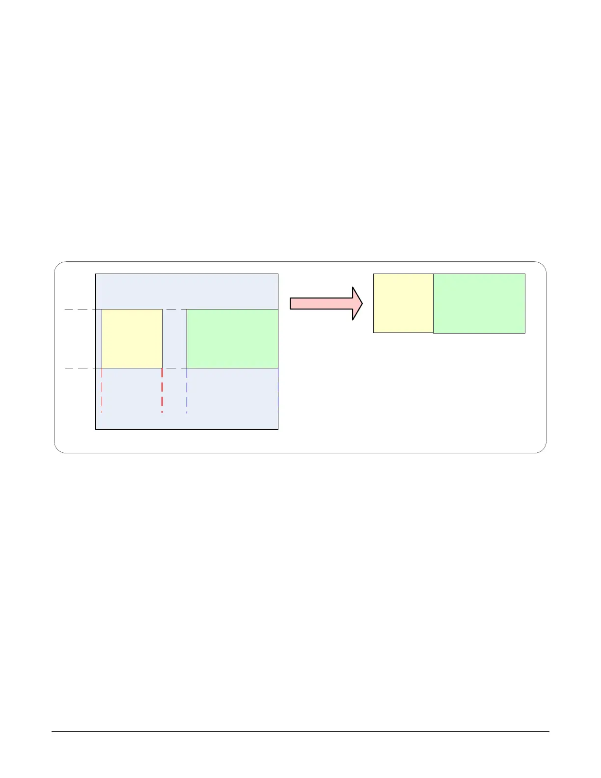
Example: Two Horizontal ROI Areas (2x1)
ROI (x1,y1)
ROI
(x2,
y1
)
ROI (x1,y1)
ROI (x2,y1)
2 ROI Areas Defined
Camera Outputs only the 2 ROI Areas
• Note that ROI(x1, y1) defines the height of any ROI in that row.
• ROI(x2, y1) can have a different width.
• The camera output image frame consists only of the two ROI areas. The user must account
for the change between ROI data for each output image row.
• The output image being smaller reduces the bandwidth requirements.

 Loading...


