Nano Series GigE Vision Camera Technical Specifications • 255
External Output AC Timing Characteristics
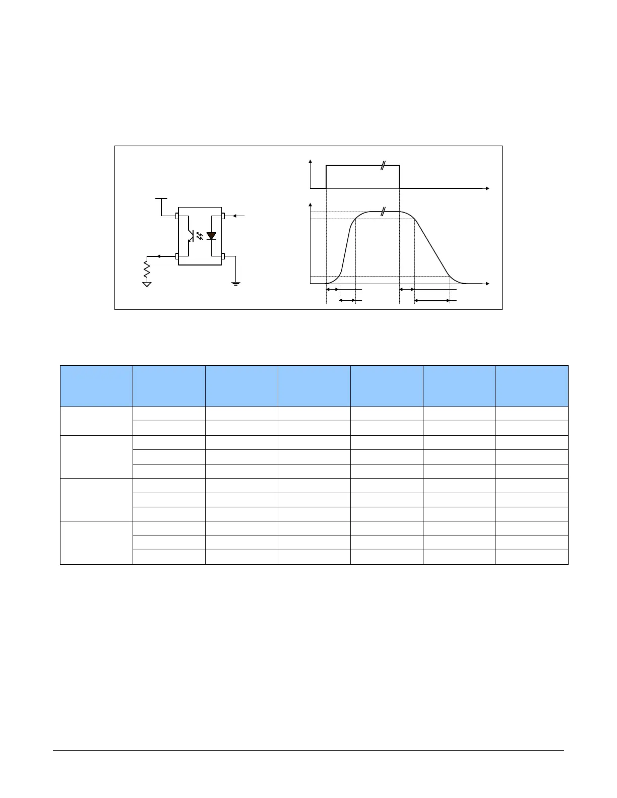
The graphic below defines the test conditions used to measure the Nano external output AC
characteristics, as detailed in the table that follows.
t
t
Output Control Signal
Output
100%
90%
10%
t
d1
t
rise
t
fall
t
d2
Output
Output Common Power
R
Load
Control
Signal
Opto-coupled Output:
AC Characteristics at an internal FPGA temperature of 83C
Note: All measurements subject to some rounding.
Output
Common
Power
Output
Current
R
load
Test
t
d1 (
µs)
Leading Delay
t
rise (
µs)
Rise Time
t
d2 (
µs)
Trailing Delay
t
fall (
µs)
Fall Time
3V 8 mA 250 ohm 0.47 2.9 11.4 26.6
16 mA 124 ohm 0.47 4.7 4.3 19.5
5V 8 mA 514 ohm 0.47 2.6 13.3 25.3
16 mA 236 ohm 0.5 7.0 4.4 17.9
21 mA 73 ohm 0.45 4.4 3.1 10.7
12V 8 mA 1.4K ohm 0.62 2.0 18.1 24.9
16 mA 677 ohm 0.54 4.8 7.5 19.9
24 mA 316 ohm 0.5 3.5 3.8 11.5
24V 8 mA 2.88K ohm 0.62 2.1 18.9 39.9
16 mA 1.42K ohm 0.63 4.7 10.9 27.1
24 mA 810 ohm 0.79 4.9 5.2 17.4
AC characteristics for optional models denoted by “G3-GM2… or G3-GC2…” part numbers is found
in addendum – AC Characteristics of 1 Input / 3 Output Models.

 Loading...


