142 • Operational Reference Nano Series GigE Vision Camera
Output Line Details
The general purpose output line signals are connected to I/O lines 3 and 4, which have the
following features for control or status indication.
• Feature set: LineInverter (RW), outputLineSource (RW), outputLinePulseDelay (RW),
outputLinePulseDuration (RW), outputLineValue (RW), outputLineSoftwareCmd (RW),
LineSelector (RW), LineName (RO), linePinAssociation (RO), LineFormat (RO), LineMode
(RO), LineStatus (RO). See Output Signals Electrical Specifications for more information.
• External outputs: Can be used as a strobe signals to control lighting or to generate
programmable pulses when specific events are generated by the camera.
• Output on Events: Each output can be set independently to one of the available event
modes defined by the ‘outputLineSource’ feature.
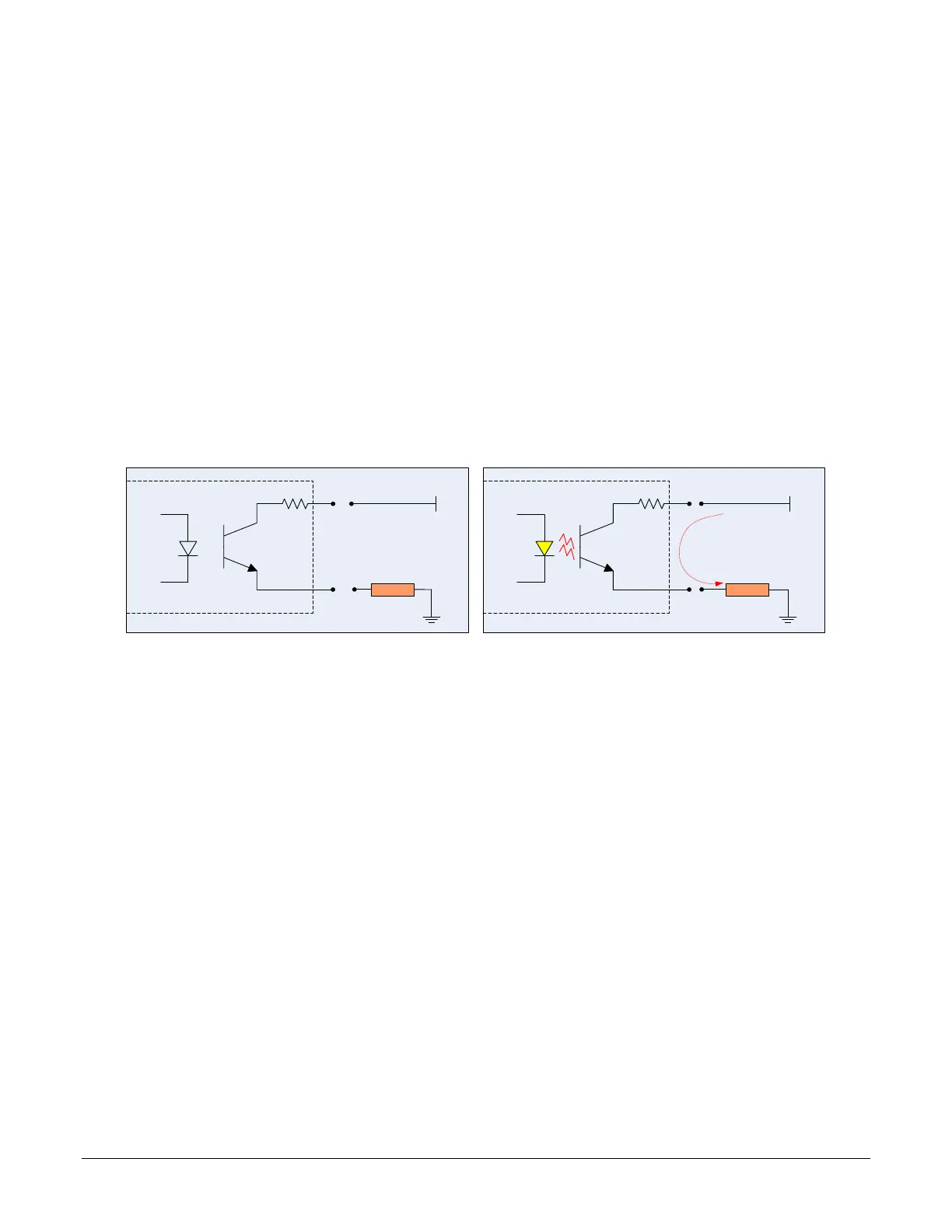
Output High and Output Low Block Diagram
Output signal lines when either in the High or Low state are shown in the following figures with an
simplified external circuit.
Camera Output
LOAD
VCC
current flow
Examples of Logic HI and Logic LO output circuits

 Loading...


