Nano Series GigE Vision Camera Technical Specifications • 247
Connectors
• A single RJ45 Ethernet connector for control and video data to the host Gigabit NIC.
Additionally for PoE, the Genie Nano requires an appropriate PoE Class 0 or Class 3 (or
greater) power source device (such as a powered computer NIC, or a powered Ethernet
switch, or an Ethernet power injector). For industrial environments, Nano supports the use
of screw lock Ethernet cables (see Ruggedized RJ45 Ethernet Cables). Note that for PoE
installations, a shielded Ethernet cable is required to provide a camera ground connection to
the controlling computer.
• Note: Connect power via the I/O or PoE, not both. Although Nano has protection,
differences in ground levels may cause operational issues or electrical faults.
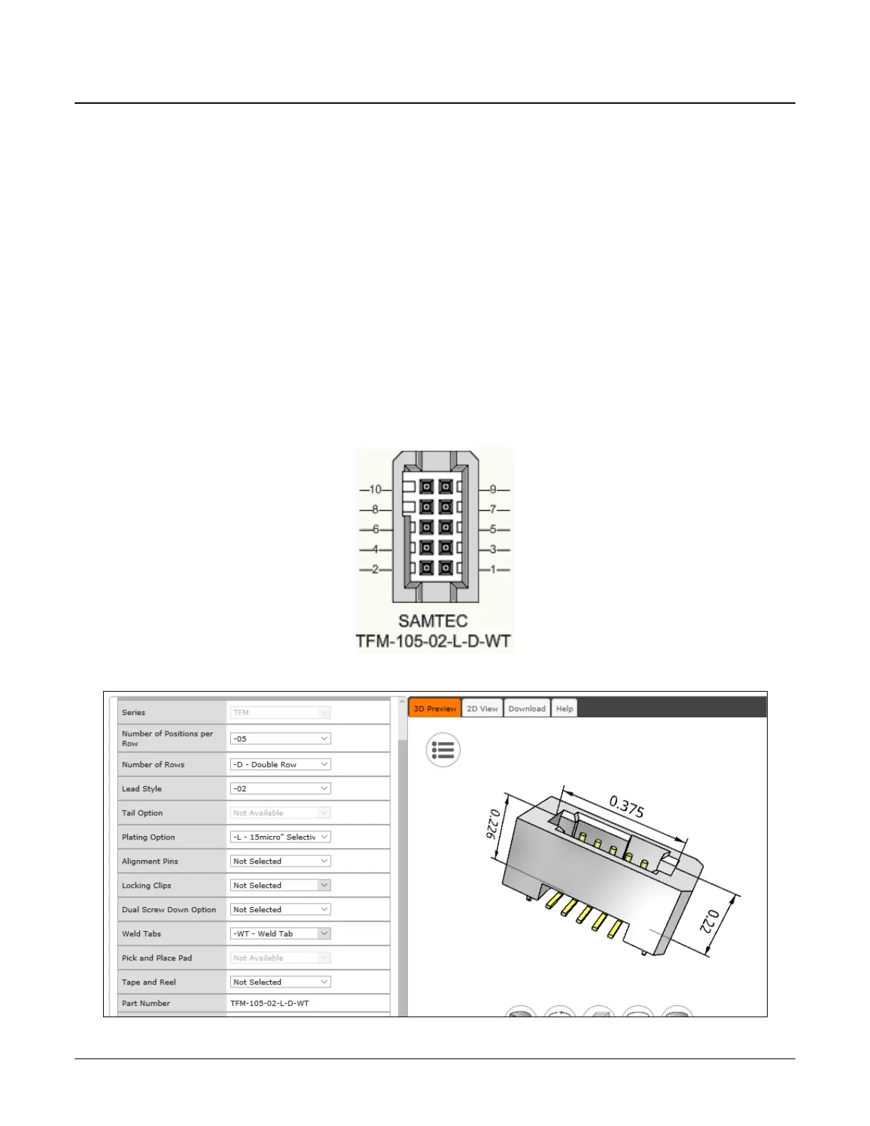
• The Nano has a single 10-pin connector (SAMTEC connector TFM-105-02-L-D-WT) for all I/O
signals and for an auxiliary DC power source. Nano supports connecting cables with
retention clips or screw locks.
• See I/O Mating Connector Sources for information about the mating connector or complete
cable solutions with retention clips. The following figure shows the pinout number
assignment (external view of the camera body connector).
Face View of the Nano Back
3D View of the camera’s connector TFM-105-02-L-D-WT

 Loading...


