Nano Series GigE Vision Camera Operational Reference • 133
Pin6=Signal – Pin4=Pwr Pin6Signal_Pin4Pwr Pin 6 is the Output Signal and Pin 4 is the common
output Power on the device connector.
Pin8=Signal – Pin4=Pwr Pin8Signal_Pin4Pwr Pin 8 is the Output2 Signal and Pin 4 is the
common output Power on the device connector.
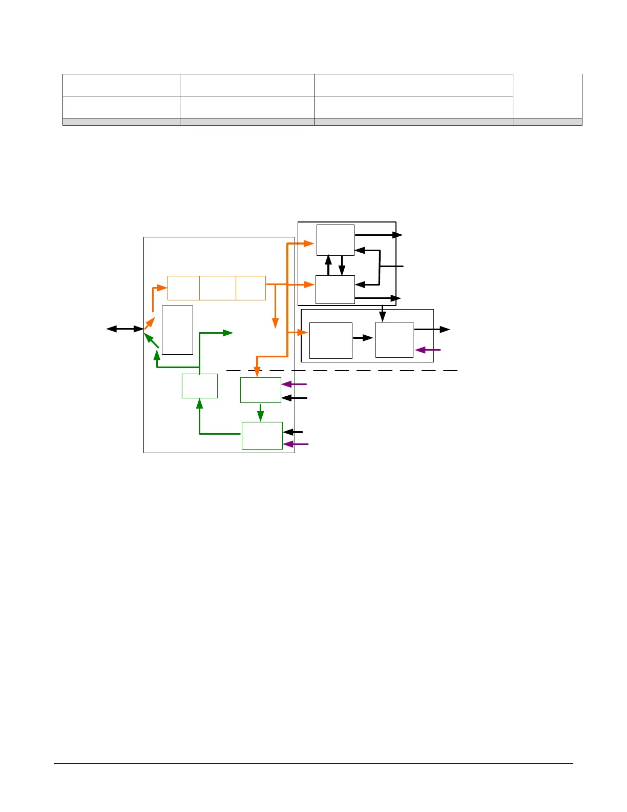
I/O Module Block Diagram
Line Selector =
Line 1 to 4
Physical
Line
Event Driven
Input
inverter
Output
inverter
Software Driven
Pulse
generator
LineStatus
Trigger
Line
Activation
Trigger Signal
Timer
TimerEnd Event
CounterEnd Event
Software Trigger
Cmd
Line
Mode
Input
or
ouput
Input
Output
Timer and Counter Module
Counter
Line
Debouncer
Event Driven
Trigger
Source
Trigger Module
Output
Line
Source
Signal Driven
Software Driven
Line
Detection
Level
Trigger Mode Details
Genie Nano image exposures are initiated by an event. The trigger event is either the camera’s
programmable internal clock used in free running mode, an external input used for synchronizing
exposures to external triggers, or a programmed function call message by the controlling
computer. These triggering modes are described below.
• Free running (Trigger Mode=Off): The Nano free-running mode has programmable
internal timers for frame rate and exposure period. Frame rate minimums, maximums, and
increments supported are sensor specific. Maximum frame rates are dependent on the
required exposure.
• External trigger (Trigger Mode=On): Exposures are controlled by an external trigger
signal where the specific input line is selected by the Trigger Source feature. External
signals are isolated by an opto-coupler input with a time programmable debounce circuit.

 Loading...


