Nano Series GigE Vision Camera Operational Reference • 193
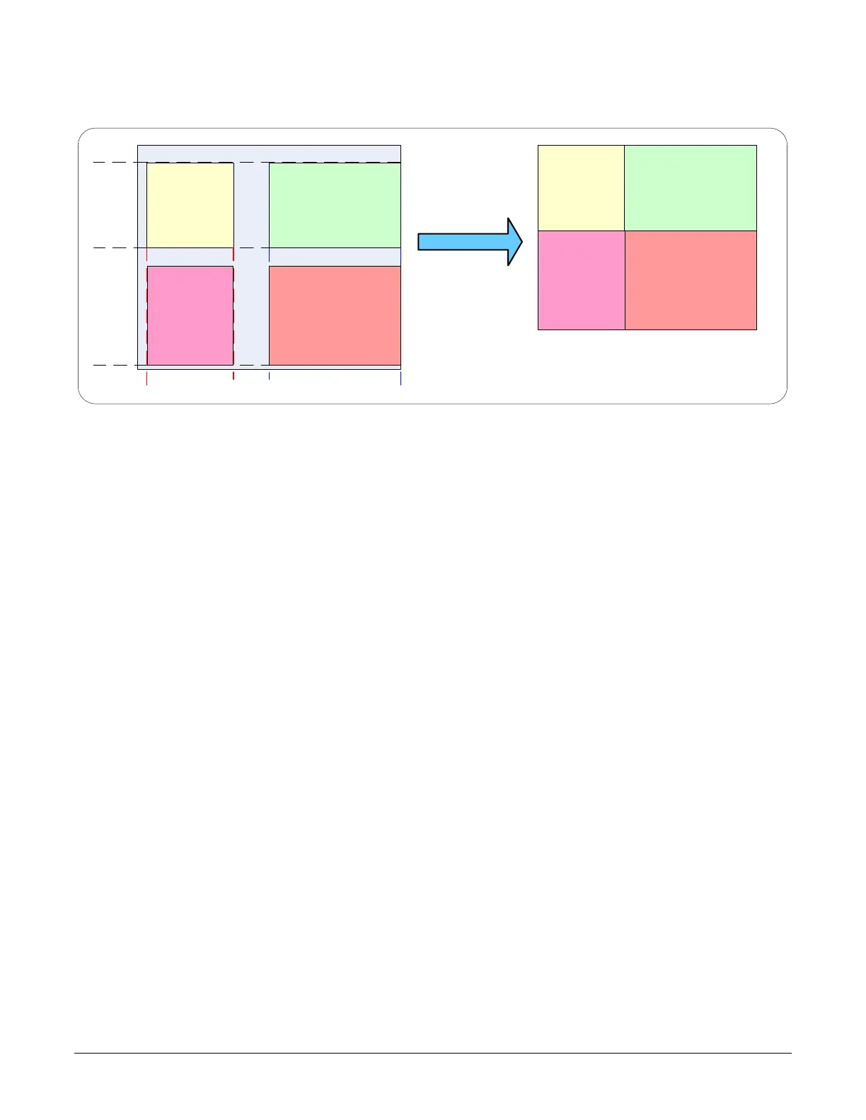
Example: Four ROI Areas (2x2)
ROI
(
x1
,y
1
)
ROI
(
x2
,y
1
)
ROI (x1,y1)
ROI (x2,y1)
4 ROI Areas Defined
Camera Outputs only the 4 ROI Areas
ROI (x1,y2)
ROI (x2,y2)
ROI (x1,y2)
ROI (x2,y2)
• Note that ROI(x1, y1) defines the height of any ROI in that row.
• ROI(x2, y1) can have a different width.
• ROI(x1, y2) can have a different height relative to ROI(x1,y1).
• The camera output image frame consists only of the ROI areas, in the same order as the
ROI rows and columns. The user must account for the change between ROI data for each
output image row.
• The output image being smaller, reduces the bandwidth requirements.
Example: Actual Sample with Six ROI Areas (3x2)
This example uses the example problem of solder inspection of certain components on a PCB. The
image below of a sample PCB shows 6 ROI areas highlighted by the yellow overlay graphics
(manually added to this example).
Note how the top row ROI areas may be larger than ideal due to height and width requirements of
ROI areas in the second row; constraints and interdependencies as defined in the preceding ROI
descriptions.

 Loading...


