196 • Operational Reference Nano Series GigE Vision Camera
Image Flip – Multi-ROI Mode
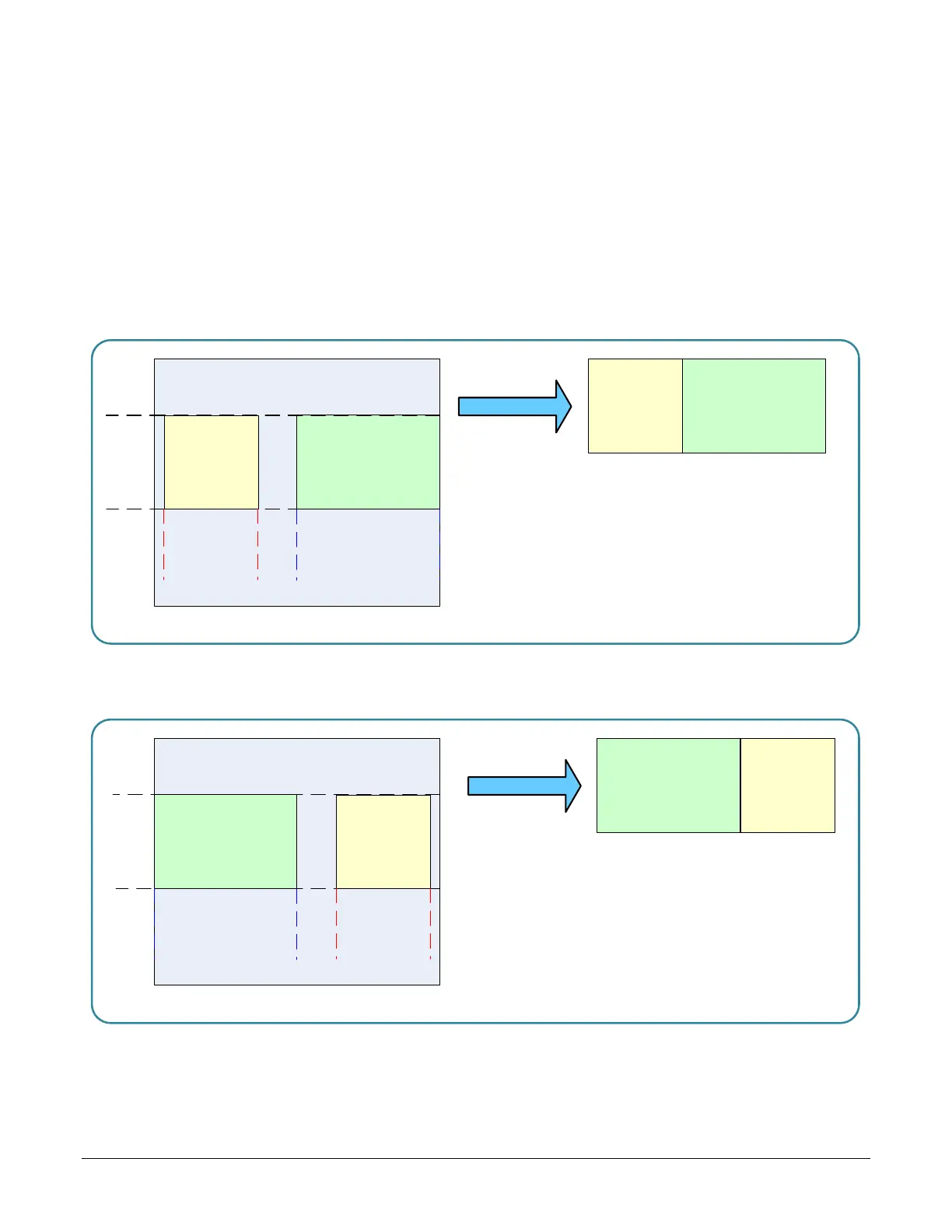
Image acquisition flips with multi-ROI enabled is implemented as follows:
• The first graphic below shows a simple multi-ROI of two areas, where the camera output is
composed of only those two areas.
• As shown in the second graphic, the multi-ROI implementation resizes the programmed ROI
areas so that the same exact image areas are output by the camera but flipped as
expected.
• Note that the ROI indexes do not transpose—just their size and offsets.
• All multi-ROI setup constraints remain as described in the previous section describing the
Multi-ROI mode.
ROI
(x
1
,y
1)
ROI (x
2,y
1)
ROI (x1,y1)
ROI (x2,y
1
)
2 ROI Areas Defined
Camera Output
ROI (x
2
,y1)
ROI (x1,
y1)
ROI (x2,y1)
ROI (x1,
y1)
2 ROI Areas After Horizontal Flip
Camera Output
Horizontal Flip with Multi-ROI

 Loading...


