Instructions for Use Fabius MRI SW 3.n 45
Operation Concept
Fresh Gas Control
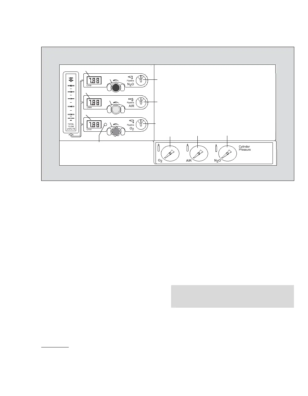
The Flow Meter and Pressure Gauge assembly is
located on the front panel of the machine below the
screen. There are three control knobs for the
adjustment of N
2O, AIR, and O2. The knobs are
labeled and color-coded, see page 48. The O2 con-
trol is also touch-coded with a fluted knob.
– to increase flow, turn the appropriate flow con-
trol knob counterclockwise
– to decrease flow, turn the appropriate flow con-
trol knob clockwise
1 N
2O flow control valve
2 AIR flow control valve
3 O
2 flow control valve
4 Total flow meter which displays the flow mea-
surement of all applied gases combined
5 N
2O electronic fresh gas flow indicator
6 AIR electronic fresh gas flow indicator
7 O
2 electronic fresh gas flow indicator
8 N
2O central supply pressure gauge
9 AIR central supply pressure gauge
10 O
2 central supply pressure gauge
11 O
2 cylinder pressure gauge*
12 AIR cylinder pressure gauge*
13 N
2O cylinder pressure gauge*
14 O
2 Low Supply Pressure Alarm LED which
flashes when the supply is below the factory set
minimum pressure, nominally 20 psi
(1.4 kPa x 100).
The displayed fresh gas flow ranges from 0 L/min
to 12 L/min. In case of a greater fresh gas flow, the
electronic fresh gas flow indicator (5, 6, 7) is blink-
ing and in the flow meter monitor window appears
the sign "+" above the graphical display of the flow
rates.
* Only used with Pin-Index connectors (not present with
threaded connectors).
NOTE
The electronic fresh gas flow meter is altitude-cor-
rected.