Operation Concept
48
Instructions for Use Fabius MRI SW 3.n
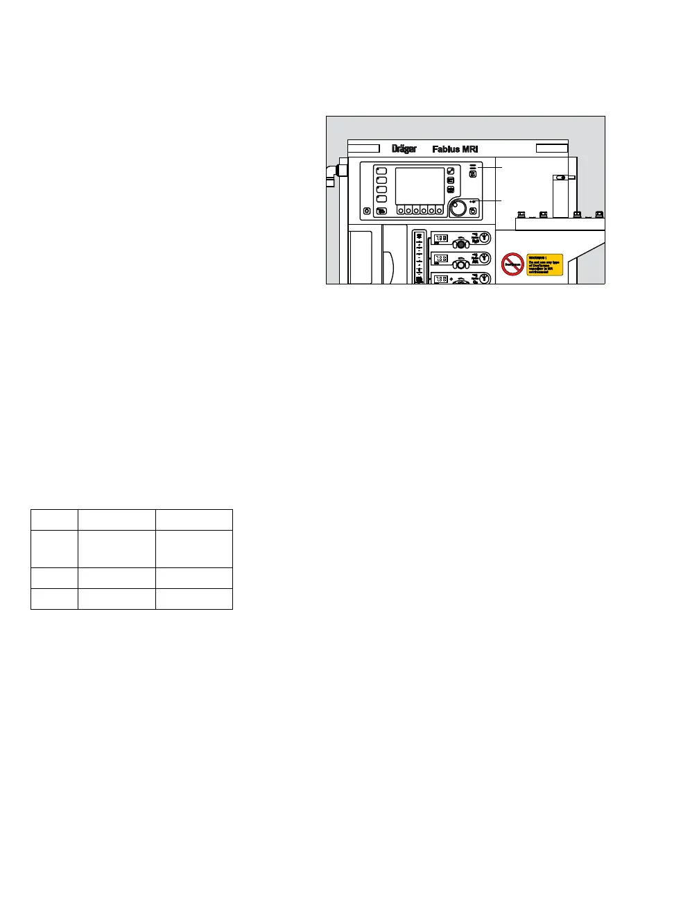
LED Indicators
A number of LED indicators are located on the front
of the machine.
1 Mains Power LED is illuminated when the
machine is connected to a Mains power source
2 Alarm LEDs are illuminated to indicate the
degree of urgency of currently active alarms:
– Warning: red blinking
– Caution: yellow blinking
– Advisory: yellow continuous
3 Two additional sets of alarm LEDs are located
at the top of the monitor housing. These LEDs
are illuminated during the same Warning and
Caution alarm conditions as the front panel
LEDs (2), but are visible from longer distances
and various vantage points.
In addition, there are small LEDs on the Standby
key and all the ventilation mode keys to indicate the
currently active mode.
Gas System Color Coding
Each connection, valve, gauge, and flow meter on
the Fabius MRI is color-coded for the appropriate
gas, as shown the table below:
Screen Color Concept
The Fabius MRI displays screen elements such as
soft keys, alarms, virtual flow tubes, and screen
backgrounds in different colors for improved visibil-
ity.
Gas USA ISO
AIR Yellow Black/White
Checkered
N
2O Blue Blue
O
2 Green White