Instructions for Use Fabius MRI SW 3.n 57
Assembly
Connecting Pipeline Supply of N2O,
AIR and O
2
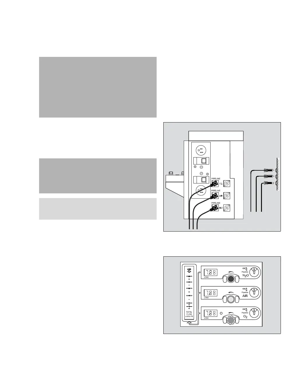
1 Connect the gas fitting on each pipeline supply
hose to the corresponding fitting on the rear of
the machine.
2 Connect the other end of each pipeline supply
hose to the appropriate functioning wall outlet.
Pipeline Pressure Gauges
Pipeline pressure gauges for N2O (1), AIR (2), and
O
2 (3) are standard. These gauges are located
directly to the right of their corresponding flow con-
trol valves. A typical pressure gauge and flowmeter
assembly is shown in the figure.
WARNING
Carefully check hoses each time you connect
a machine to a wall outlet to ensure that both
ends of the hose are indexed for the same gas.
Pipeline delivery hoses used between wall
outlets and anesthesia machines have caused
accidents when, during assembly, an oxygen
fitting was placed on one end of the hose and
a nitrous oxide fitting on the other end.
CAUTION
To ensure that gas supplies are at adequate pres-
sure, pipeline pressure gauges must indicate
steady pressures of between 41 and 87 psi (2.8
and 6 kPa x 100).
NOTE
The loss of the pipeline supply could cause the
loss of combined devices.