Instructions for Use Fabius MRI SW 3.n 5
Contents
Contents
Working with These Instructions for Use. . . . . 2
Trademarks . . . . . . . . . . . . . . . . . . . . . . . . . . . . . 3
Definitions. . . . . . . . . . . . . . . . . . . . . . . . . . . . . . . 3
Abbreviations and Symbols . . . . . . . . . . . . . . . . . 3
Notice . . . . . . . . . . . . . . . . . . . . . . . . . . . . . . . . . . 3
Definition of target groups . . . . . . . . . . . . . . . . . . 3
Magnetic Resonance (MR) Definitions . . . . . . . . . 4
For Your Safety and that of Your Patients . . . . 7
Intended Use. . . . . . . . . . . . . . . . . . . . . . . . . . . 15
Intended Use . . . . . . . . . . . . . . . . . . . . . . . . . . . 16
Indications for Use . . . . . . . . . . . . . . . . . . . . . . . 16
Restriction of Distribution . . . . . . . . . . . . . . . . . . 16
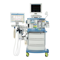
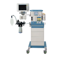
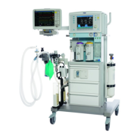
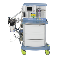
System Overview . . . . . . . . . . . . . . . . . . . . . . . 17
Front View . . . . . . . . . . . . . . . . . . . . . . . . . . . . . 18
Compact Breathing System (Top View) . . . . . . . 19
Rear View (Pin-Index Connector) . . . . . . . . . . . 20
Interface Panel . . . . . . . . . . . . . . . . . . . . . . . . . 21
Vaporizers (Optional) . . . . . . . . . . . . . . . . . . . . . 22
Vaporizer Exclusion Systems . . . . . . . . . . . . . . . 22
Auxiliary Oxygen Flowmeter. . . . . . . . . . . . . . . . 24
O
2 Flush Button . . . . . . . . . . . . . . . . . . . . . . . . . 25
APL Valve . . . . . . . . . . . . . . . . . . . . . . . . . . . . . . 26
Writing Table. . . . . . . . . . . . . . . . . . . . . . . . . . . . 27
Communication Port. . . . . . . . . . . . . . . . . . . . . . 28
Teslameter . . . . . . . . . . . . . . . . . . . . . . . . . . . . . 29
Accessory Mounting . . . . . . . . . . . . . . . . . . . . . . 30
Abbreviations . . . . . . . . . . . . . . . . . . . . . . . . . . . 32
Symbol Definition . . . . . . . . . . . . . . . . . . . . . . . . 33
Operation Concept . . . . . . . . . . . . . . . . . . . . . . 37
Control Panel . . . . . . . . . . . . . . . . . . . . . . . . . . . 38
The Screen Display . . . . . . . . . . . . . . . . . . . . . . 39
Rotary Knob . . . . . . . . . . . . . . . . . . . . . . . . . . . . 40
Fixed Function Keys. . . . . . . . . . . . . . . . . . . . . . 40
Soft Keys . . . . . . . . . . . . . . . . . . . . . . . . . . . . . . 41
Fresh Gas Control . . . . . . . . . . . . . . . . . . . . . . . 45
LED Indicators . . . . . . . . . . . . . . . . . . . . . . . . . . 48
Gas System Color Coding . . . . . . . . . . . . . . . . . 48
Screen Color Concept . . . . . . . . . . . . . . . . . . . . 48
Assembly. . . . . . . . . . . . . . . . . . . . . . . . . . . . . . 49
Activating the Battery . . . . . . . . . . . . . . . . . . . . 50
Fitting the CO
2 Absorber on the Compact
Breathing System . . . . . . . . . . . . . . . . . . . . . . . 51
Inserting the Flow Sensor . . . . . . . . . . . . . . . . . 52
Connecting the Compact Breathing System . . . 52
Installing the Drägersorb CLIC Adapter . . . . . . 54
Connecting the Waste Gas Outlet Port . . . . . . . 55
Installing the Breathing Bag Extension and
Bag . . . . . . . . . . . . . . . . . . . . . . . . . . . . . . . . . . 56
Connecting Pipeline Supply of N
2O, AIR and
O
2 . . . . . . . . . . . . . . . . . . . . . . . . . . . . . . . . . . . 57
Connecting the Reserve Gas Cylinders for
N
2O, AIR and O2 ( for Pin-Index Mounting) . . . 58
Connecting the AGSS Anesthetic Gas
Scavenging System. . . . . . . . . . . . . . . . . . . . . . 61
Connecting the Passive Scavenger . . . . . . . . . 63
Connecting the Suction System . . . . . . . . . . . . 64
Connecting the Breathing Hoses and
Breathing Bag . . . . . . . . . . . . . . . . . . . . . . . . . . 65
Inserting a new O
2 Sensor Capsule . . . . . . . . . 68
Connecting the O2 Sensor . . . . . . . . . . . . . . . . 68
Connecting the Pressure Sensor . . . . . . . . . . . 69
Connecting the Breathing Pressure Gauge. . . . 69
Connecting the Flow Sensor . . . . . . . . . . . . . . . 70
Connecting the APL Bypass and PEEP/P
MAX
Hoses . . . . . . . . . . . . . . . . . . . . . . . . . . . . . . . . 70
Preparing the Ventilator. . . . . . . . . . . . . . . . . . . 71
Ventilator Safety Features . . . . . . . . . . . . . . . . . 71
Installing Vaporizers . . . . . . . . . . . . . . . . . . . . . 72
Connecting Auxiliary Equipment . . . . . . . . . . . . 74
Auxiliary power outlets . . . . . . . . . . . . . . . . . . . 75
Positioning the Fabius MRI at MRT System . . . 76
Connecting AC Power . . . . . . . . . . . . . . . . . . . . 78
Checklist . . . . . . . . . . . . . . . . . . . . . . . . . . . . . . 79
Daily and Pre-use Checkout . . . . . . . . . . . . . . . 80
Getting Started. . . . . . . . . . . . . . . . . . . . . . . . . 81
Powering-Up the Machine . . . . . . . . . . . . . . . . . 82
Power-Up Standby Screen . . . . . . . . . . . . . . . . 83
Checking Readiness for Operation . . . . . . . . . . 83
Operation . . . . . . . . . . . . . . . . . . . . . . . . . . . . . 85
Power-Up Standby Screen . . . . . . . . . . . . . . . . 86
Setting Fresh Gas Flow. . . . . . . . . . . . . . . . . . . 86
Setting Vaporizer Concentration . . . . . . . . . . . . 88