Maintenance 4. Cable
150 N6 Rev.2
subsequent steps are described with the standard model’s cable unit.
For cleanroom model, a yellow air
tube is included in the cable unit.
Remove the following covers:
Arm #4 side cover (2 covers)
Joint #4 inside cover Joint #4 outside cover Joint #4 side covers (2 covers)
Arm #3 cover Arm #3 inside cover Arm #2 cover (2 covers)
Joint #2 cover Joint #2 outside cover
Arm #1 inside cover Joint #1 cover Base cover
Maintenance 3. Covers.
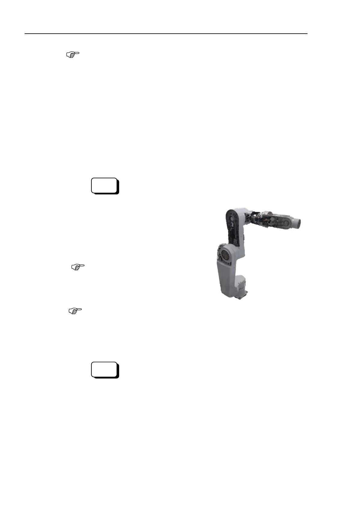
Release the brakes of each joint and move the Manipulator to the orientation as
shown below.
Command
>Brake off,
[the number (from 2 to 6) corresponding to the
arm whose brake will be turned off]
Joint #1
Joint #2
Joint #3
Joint #4
Joint #5
°
°
90°
°
°
When releasing the brake, the arm may rotate
by its own weight.
Normally, release the brake of joints one by one.
Take extra care if you need to
release the brakes of two or more joints simultaneously.
Releasing the brakes of
two or more joints simultaneously may cause hands and fingers to be caught and/or
equipment damage to or malfunction of the Manipulator as the arms of the
Manipulator may move in unexpected directions.
>Brake On,
[The number (from 2 to 6) corresponding to the arm
whose brake will be turned on]

 Loading...


