Maintenance 4. Cable
226 N6 Rev.2
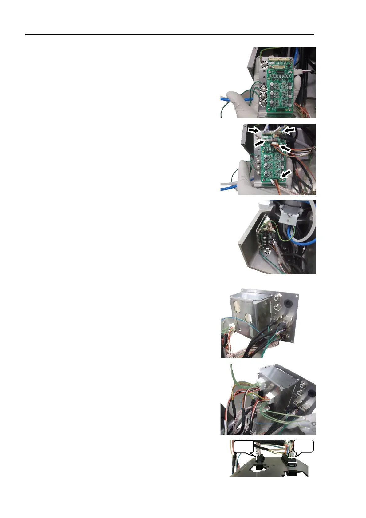
Install the four ground wire terminals except
the connector X11, X12 to the board fixing
plate.
Cross recessed binding head machine screws:
4-M4×8
Tightening torque: 0.9 ± 0.1 N·m
Connect the connectors to the encoder board 1
and the brake board.
Connectors:
EB01_CN1, EB01_CN3, EB0x_CN2
BRK_CN1, BRK_CN2
Install the board fixing plate in the back of the
base.
Hexagon socket head cap bolts: 2-M3×6
Tightening torque: 2.0 ± 0.1 N·m
Connect the connectors to the base side plate.
Connectors: Ether1, Ether2, D-sub, SW1
Connect the connectors to the box
-shaped
Connectors: X11, X12, X010, BR010
Refer to the right picture for installation
direction of black colored connectors (X010,
BR010).

 Loading...


