Maintenance 4. Cable
N6 Rev.2 251
6
Unit
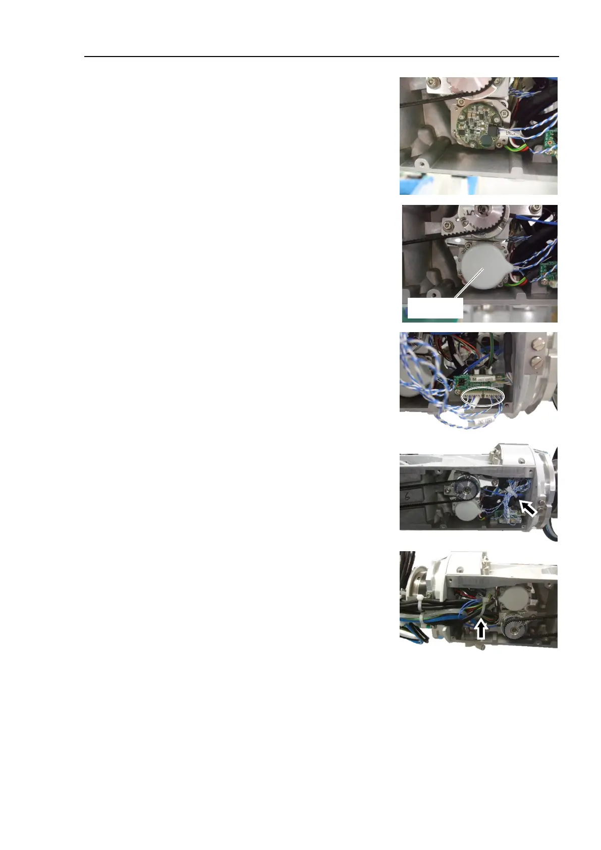
the relay cable 1 to
Connector: ENC_x
Install the encoder cover.
Cross recessed head screws: 3-M2.5×6
Tightening torque: 0.2 ± 0.1 N·m
Connect the connector to the
encoder board 4.
Connector: EB0x_CN2
Bundle the cables with the cable tie to prevent
the cables from interfering with the pulley or
belt.
Cable ties (AB200) × 2
Install the Arm #4 side cover (2 covers).
For details, refer to Maintenance 3.14 Arm #4 Side Cover.
7)
For details, refer to Maintenance 4.6. M/C Cable.
or the Joint #6.
For details, refer to Maintenance 8. Calibration.

 Loading...


