Maintenance 5. Actuator Units
288 N6 Rev.2
Installation
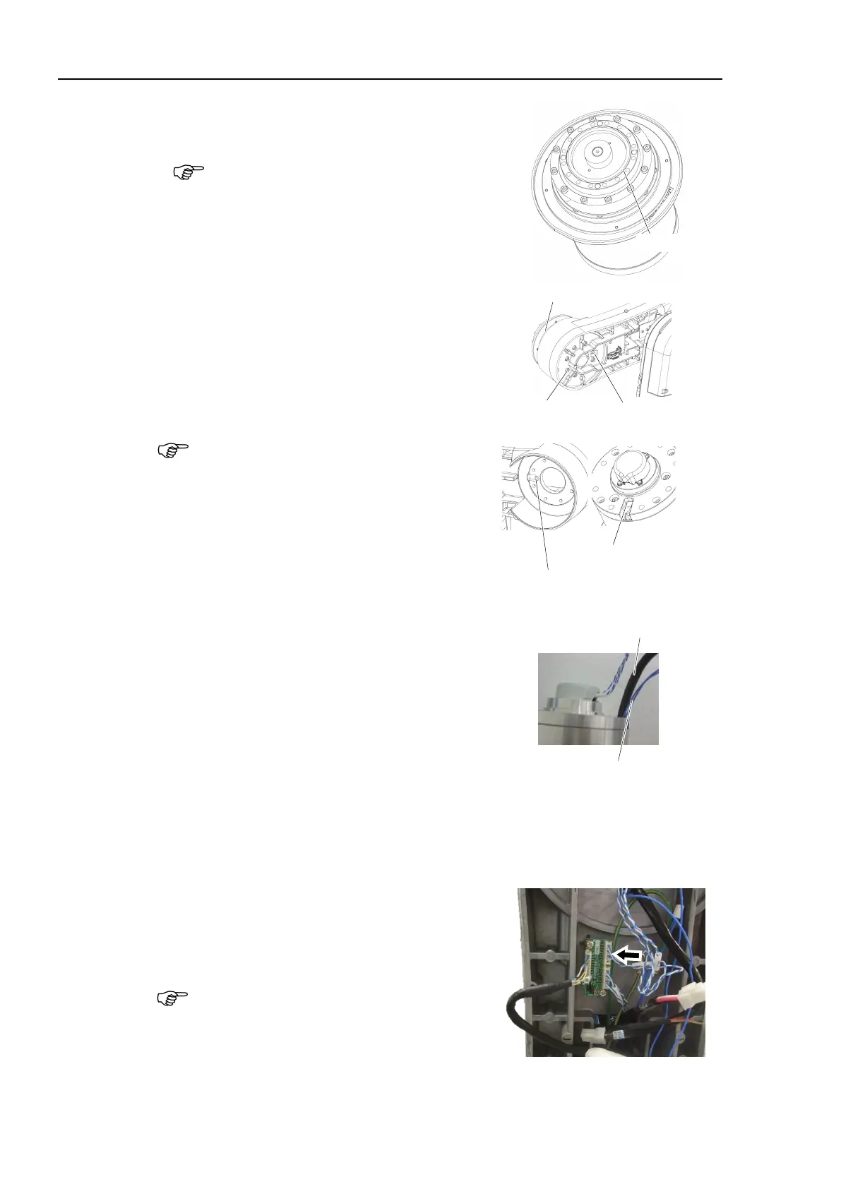
Joint #3
Actuator Unit
N6-A1000**
the attached O-ring on the Joint #3
coat of grease to the O-ring.
Grease: SK-1A
Install the Joint #3 actuator unit to the Arm
#2.
Hexagon socket head cap bolts:
8-M6×35 (with plain washer)
Tightening torque: 18 ± 0.9 N·m
it, make sure to align the
n the Arm #2 and the groove
n the Joint #3 actuator unit.
Pass the brake cable and the motor cable of
the Joint #3 actuator unit through the hole of
the Arm #2.
Be careful not to get the cables caught
in the
and the actuator unit.
Be sure to have at least 2 people to perform
the operation since the parts being heavy
.
Do not apply excessive shock to the parts.
8-M6×35
(with plain washer)
Protruding part of the Arm #2
Groove of the actuator unit
Install the robot arm and the cable unit.
For details, refer to the Removal steps (25), (26), (29) through (52) in
Maintenance 4.1 Cable Unit (N6-A1000*): Cable direction Standard
(backward).
the connector to the encoder board 2.
Connector:
EB0x_CN2 (Joint #3 side)
Be careful that the jumper pins on the board
do not come off.

 Loading...


