Maintenance 5. Actuator Units
N6 Rev.2 297
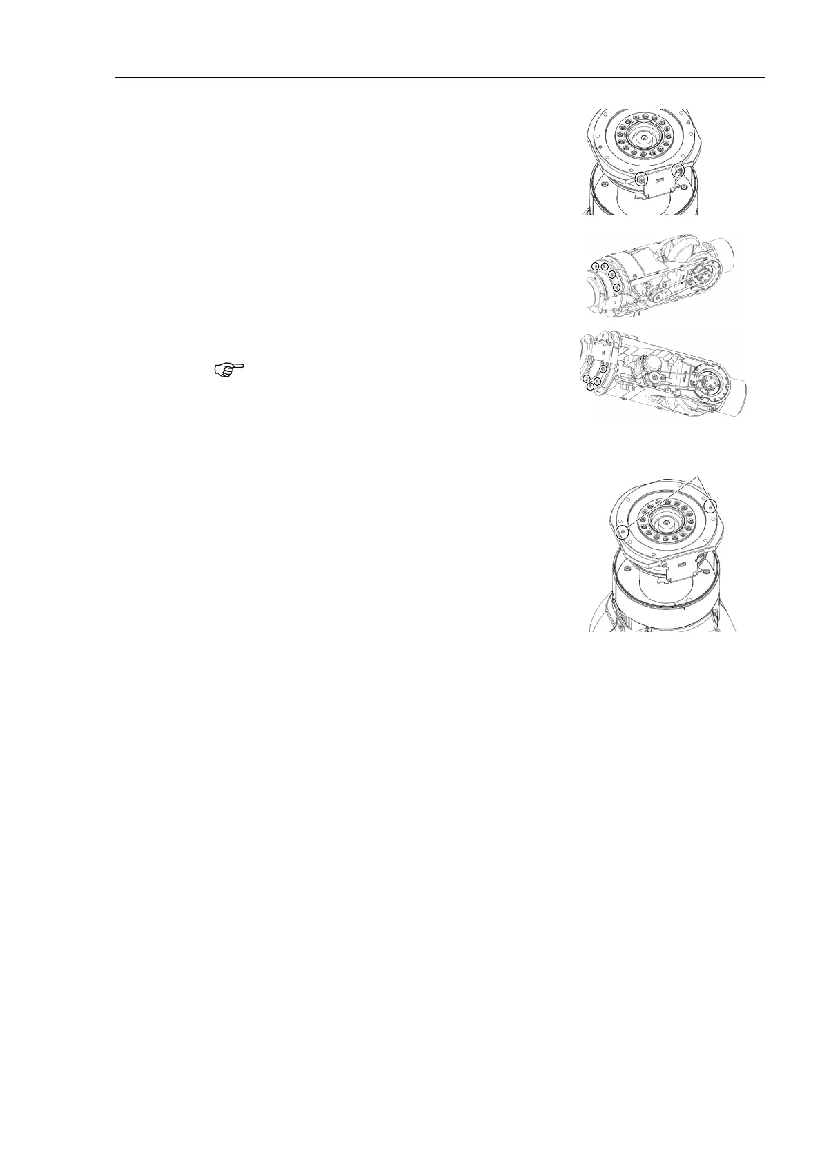
Install the cable fixing plates.
Hexagon socket head cap bolts:
2-M4×8 (with plain washer)
Tightening torque: 4.0 ± 0.2 N·m
Hexagon socket head cap bolts:
8-M4×20 (with plain washer)
Tightening torque: 5.5 ± 0.25 N·m
Be sure to have at least 2 people to perform the
operation since the parts
being heavy.
Confirm that the two pins are installed on the
Joint #4 flange. Then install the
Arm #4 to
align the pins with the Joint #5 and #6 units.
-ring properly.
Be careful not to get the cables caught
in the
.
For more details, refer to the following sections:
Installation
steps (40) through (42), (44)
through (52)
Maintenance 4.1 Cable Unit
(N6-A1000*): Cable direction
Standard (backward).
Installation steps (43) through (45), (47
through (55)
Maintenance 4.1 Cable Unit
(N6-A850*R): Cable direction
Standard (backward).
Install the following covers:
Arm #4 side cover (2 covers), Joint #4 inside cover, Joint 4 outside cover
Joint #4 side cover (2 covers), Arm #3 cover
For details, refer to Maintenance 3. Covers.
For details, refer to Maintenance 8. Calibration.

 Loading...


