Maintenance 5. Actuator Units
296 N6 Rev.2
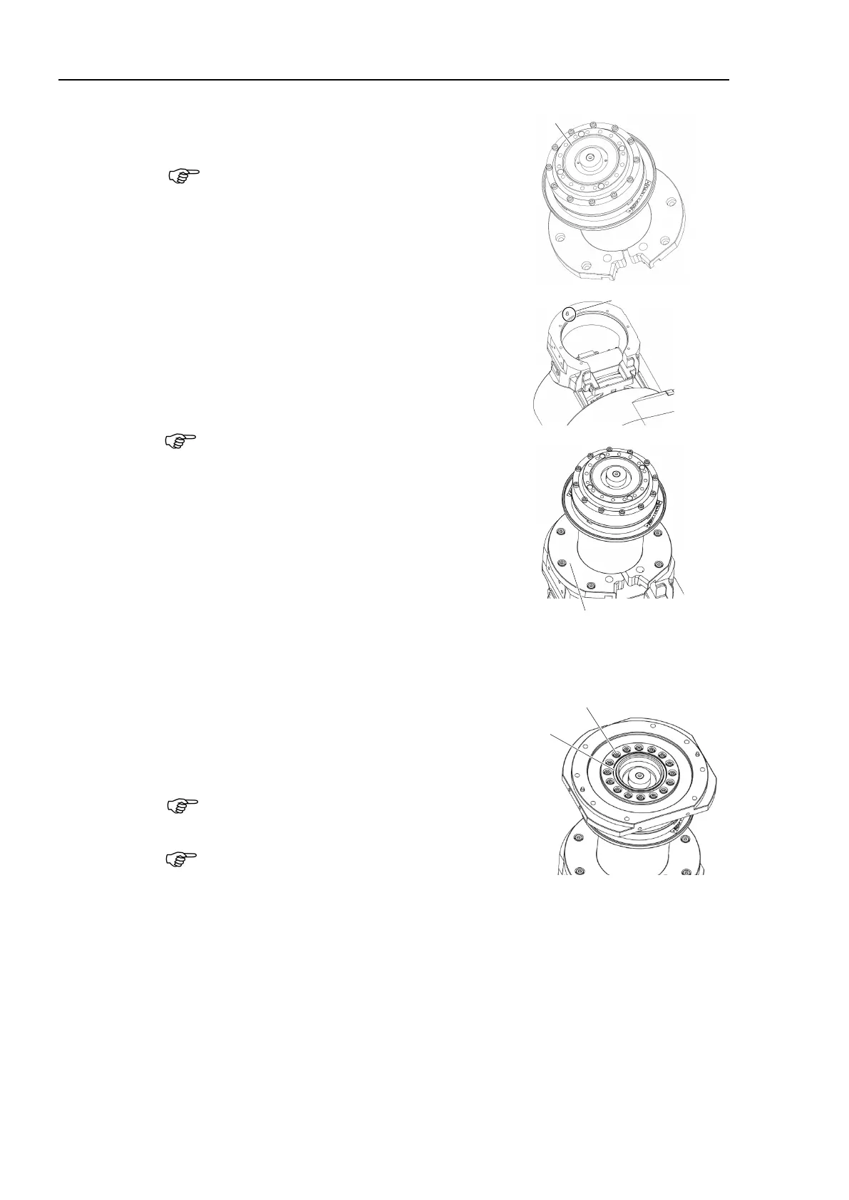
the attached O-ring to Joint #4 actuator
grease to the O-ring.
Grease: SK-1A
Confirm that the positioning pin is installed on
the Arm #3. Install the Joint #4 actuator unit.
Hexagon socket head cap bolts:
7-M4×15 (with plain washer)
Tightening torque: 5.5 ± 0.25 N·m
When installing it, make sure to align the pin
with the Joint #4 of the actuator unit.
Be careful not to get the cables caught
in the
.
Pass the cables of the Joint #4 actuator unit to
be out from the Arm #3
board side.
7-M4×15 (with plain washer)
Connector: PW4, BR4, EB0x_CN2
Install the Joint #4 flange.
Hexagon socket head cap bolts:
16-M3×20 (with plain washer)
Tightening torque: 2.4 ± 0.1 N·m
-ring properly.
After installing the Joint #4 flange, install the
O
-ring on the Joint #4 flange.
O-ring Inner diameter ø 47.5 mm
Wire diameter ø 2.0 mm
Apply a thin coat of grease to the O
-ring.
Grease: SK-1A
16-M3×20 (with plain washer)

 Loading...


