Maintenance 5. Actuator Units
N6 Rev.2 321
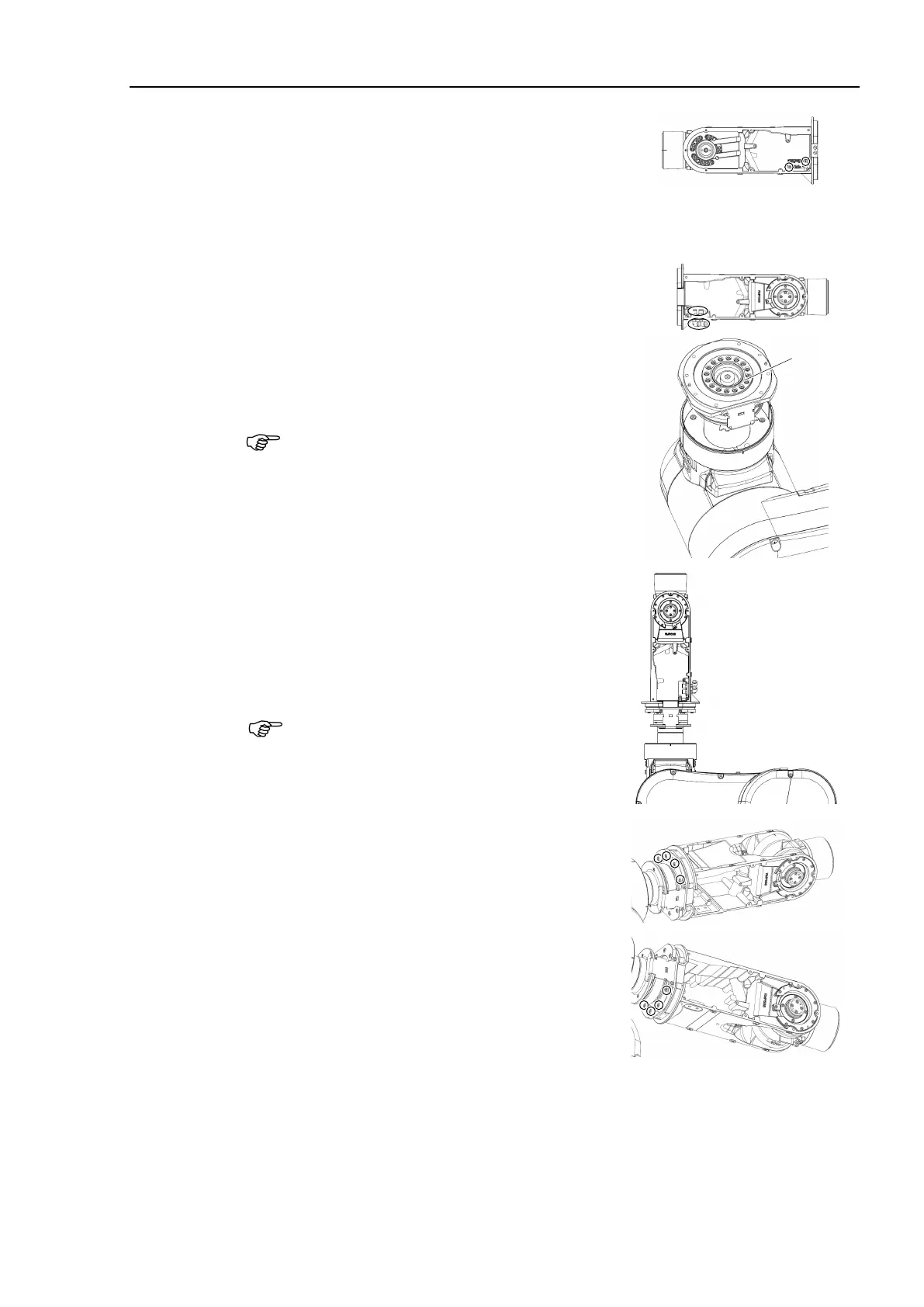
Install the encoder board #4 to the Joint #5 and
#6 units.
Cross recessed binding head machine screws:
2-M3×6
Tightening torque: 0.45 ± 0.05 N·m
Install the air tube fittings to the Joint #5 and #6
units.
-ring to the Joint #4 flange.
O-ring Inner diameter ø 47.5 mm
Wire diameter ø 2.0 mm
thin coat of grease to the O-ring.
Grease: SK-1A
Install the Joint #5 and #6 units on the Joint #4
actuator unit.
Hexagon socket head cap bolts:
8-M4×20 (with plain washer)
Tightening torque: 5.5±0.25 N·m
Be sure to have at least 2 people to perform the
operation since the parts being heavy
.
Confirm that the two pins are installed on the
Joint #4 flange. When installing it, make sure to
align the pins with the Joint #5 and #6 units.
he O-ring properly.
Be careful not to get the cables caught
in the
the actuator unit.

 Loading...


