Customizable logic (Mode selection)
Customizable logic: Step 1 to 14 (Mode setting)
Customizable logic: Output signal 1 to 10 (Output selection)
Customizable logic: Output signal 1 to 10 (Function selection)
Customizable logic: Timer monitor (Step selection)
Customizable logic: The coefficients of the approximate formula
Customizable logic: Task process cycle setting
Customizable logic: Operating point 1 to 3
Customizable logic: Auto calculation of the coefficients of the approximate formula
Customizable logic: User parameter 1 to 20
Customizable logic: Storage area 1 to 5
Customizable logic: Step 15 to 200 setting
■ Customizable Logic (Mode selection) (U00)
U00 specifies whether to enable the sequence configured with the customizable logic function or disable it to run
the inverter only via its input terminals or others.
U00 data Function
0 Disable
1 Enable (Customizable logic operation)
The
ecl
alarm occurs when changing U00 from 1 to 0 during operation.
■ Customizable Logic (Mode Setting) (U01 to U70, U190 to U195)
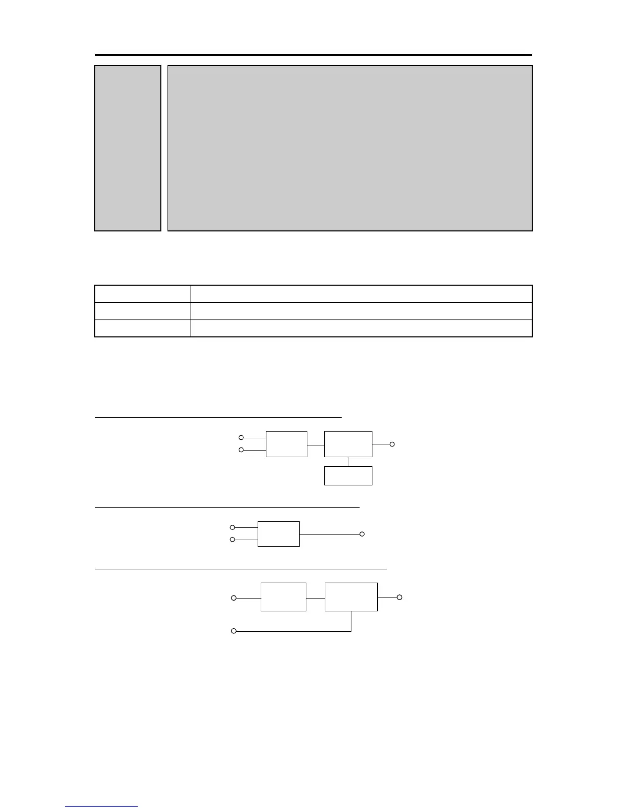
In the customizable logic, the steps are categorized in the following three types:
[Input: digital] Block selection (U01, U06, U11, etc.) = 1 to 1999

 Loading...


