2.2 Wiring
2-46
Table 2.2-30 Functional Description of Control Circuit Terminals (continued)
Classification
Terminal
symbol
Terminal name
Functional description
Digital Input
[CM] Digital
common
This terminal is the common terminal for digital input signals.
This terminal is insulated from terminals [11] and [CMY].
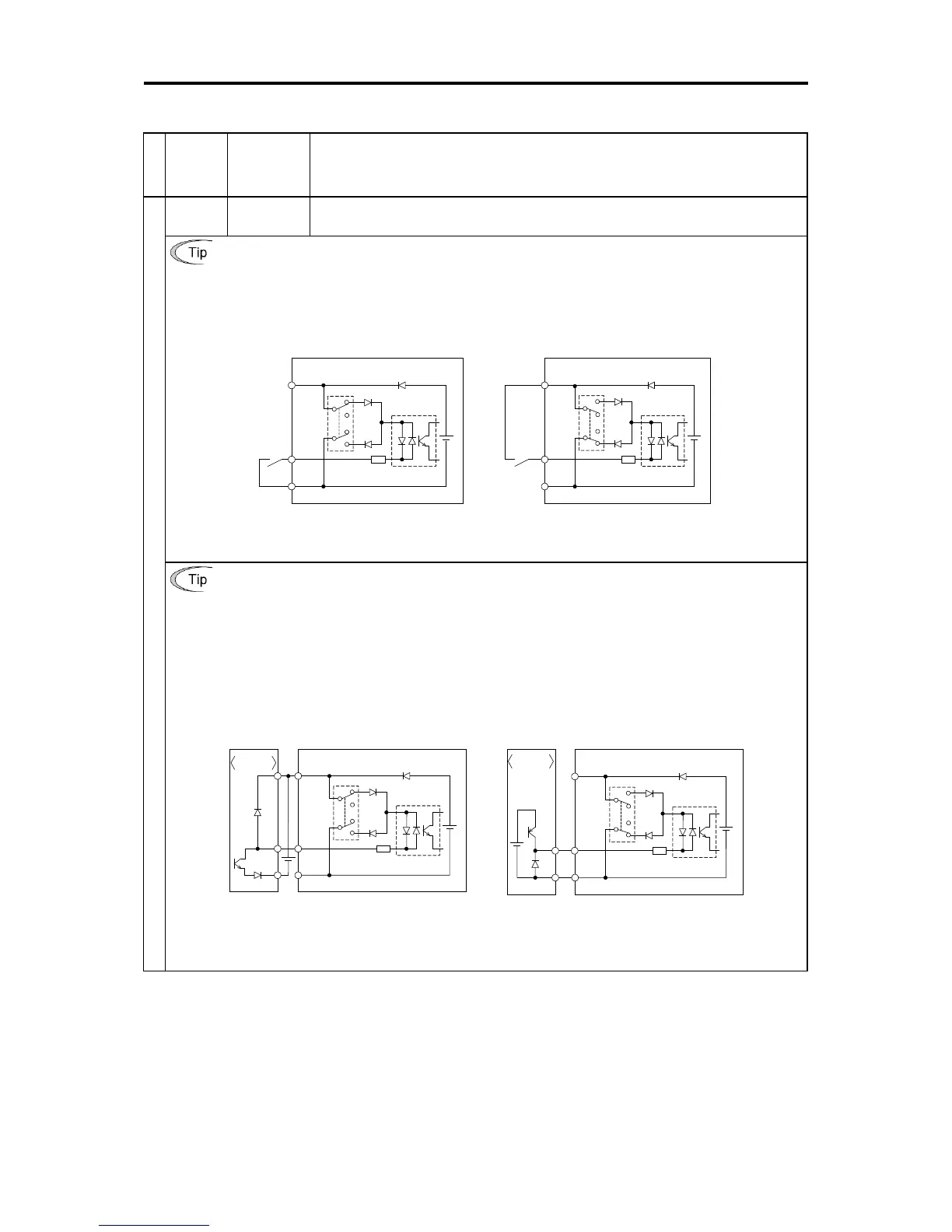
When turning terminals [FWD], [REV], [X1] to [X5] ON and OFF using relay contacts
Figure 2.2-16 shows an example of the circuit configuration using relay contact. Circuit (a) in Figure 2.2-16
shows the circuit configuration when the switch (SW1) is on the sink side and circuit (b) shows the circuit
configuration when the switch is on the source side.
Caution: Use a relay which will not have contact failures (high contact reliability).
(Recommended product: Fuji Electric’s control relay type: HH54PW)
PLC
Photo coupler
CM
<Control circuit block>
X1 to X5,
FWD,
REV
DC+24 V
SOURCE
SINK
PLC
Photo coupler
CM
<Control circuit block>
X1 to X5,
FWD,
REV
DC+24 V
SOURCE
SINK
(a) Switch on sink side (b) Switch on source side
Figure 2.2-16 Circuit Configuration Example Using Relay Contact
When turning terminals [FWD], [REV], [X1] to [X5] ON and OFF using the programmable controller
Figure 2.2-17 shows an example of the circuit configuration using programmable controller. Circuit (a) in Figure
2.2-17 shows the circuit configuration when the switch (SW1) is on the sink side and circuit (b) shows the circuit
configuration when the switch is on the source side.
In circuit (a), terminals [FWD], [REV], [X1] to [X5] can be turned ON/OFF by shorting/opening the open
collector transistor output of the programmable controller using the external power supply. Follow the
instructions below when using this type of circuit.
• Connect the + side of the external power supply which is insulated from the programmable controller power
supply to terminal [PLC].
• Do not connect the inverter’s [CM] terminal and the common terminal of the programmable controller.
PLC
Photo coupler
CM
<Control circuit block>
X1 to X5,
FWD, REV
DC+24 V
Programmable
controller
SOURCE
SINK
PLC
Photo coupler
CM
<Control circuit block>
X1 to X5,
FWD, REV
DC+24 V
<Programmable
controller>
SOURCE
SINK
(a) Switch on the sink side (b) Switch on the source side
Figure 2.2-17 Circuit Configuration Example Using Programmable Controller
Refer to “2.2.8 Operating slide switches” for more information on the switches.

 Loading...


