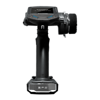
Mode Switch
Use the small plastic screwdriver that was
included with your receiver.
Switch is also used for the CH mode selection.
Receiver R3008SB
Connector
"1 through 6": outputs for the channels 1
through 6
"7/B": outputs of 7 channels and power.
"8/SB": outputs of 8 channels or S.BUS port.
[S.BUS Servo S.BUS Gyro ]
*When using 8/SB as S.BUS, you have to set
CH MODE of the following page to mode B/D/E.
"S.BUS2": outputs of S.BUS2 port.
[S.BUS2 Servo S.BUS2 Gyro Telemetry Sensor ]
*When using 8 or more channels, use an S.BUS
function or use a second R3008SB and link both
to your transmitter.
Connector insertion
Firmly insert the connector in the direction
shown in the gure. Insert the S.BUS2 by turning
it 90 degrees.
+
-
Receiver
Danger
Do not connect either a switch
or battery in this manner.
Danger
Don't connect in the manner shown in the
gure above.
*If connected in this way, the device will short-circuit. A
short circuit may cause abnormal heating, re, and/or burns.
Don't connect servo for conventional
system to S.BUS/S.BUS2 port.
*Digital servos for conventional systems do not operate.
*Analog servos may cause abnormal heat, res, and/or burns.
Warning
S.BUS2 connectors
Don't connect an S.BUS servo / gyro to
S.BUS2 connector.
LED Monitor
This monitor is used to check the CH mode of
the receiver.
Before using the receiver, be sure to read the precautions
listed in the following pages.
Extra Voltage Connector
Battery
7CH servo
Y-harness
(7/B)
Receiver Nomenclature