GAMATRONIC ELECTRONIC INDUSTRIES LTD.
+
SA: 20, 30 and 40 kVA, Release 2.1
87
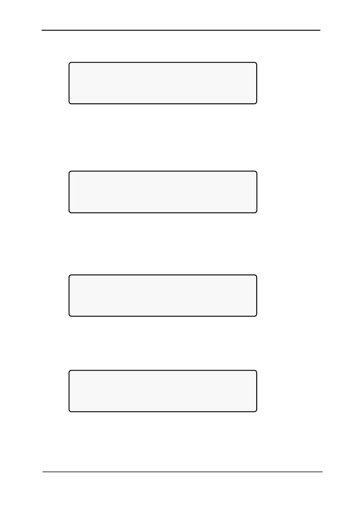
3. Adjust the measured value using the arrow keys, and press Ent to update:
[Main Menu > SETUP > (password) > Module conf. > DC Calibration > Ent]
MODULE V. CALIB – 15 Sec to expire
####### Press ENTER To UPDATE ######
MEASURED VALUE: 432.0V
Figure 151: Enter measured value
9.9.8 Calibrating AC Voltage
1. Select AC Calibration:
[Main Menu > SETUP > (password) > Module conf.]
1. Num of phase 5.Output Adjust
2. Module/s frequency 6.Frequency Limits
3. Module/s voltage 7.DC Calibration
4. Update Vo/Fr/ph 8.AC Calibration
Figure 152: Module Config. setup menu
2. Select either Calibrate INPUT Voltage or Calibrate OUTPUT Voltage and then
press Ent:
[Main Menu > SETUP > (password) > Module conf. > AC Calibration]
--- MODULES AC VOLTAGE CALIBRATION ---
SELECT – 1: Calibrate INPUT Voltage
SELECT – 2: Calibrate OUTPUT Voltage
Then press ENTER to continue
Figure 153: Calibrate INPUT or OUTPUT Voltage
3. Adjust the measured value using the arrow keys, and press Ent to update:
[Main Menu > SETUP > (password) > Module conf. > AC Calibration > Ent]
MODULE V. CALIB – 15 Sec to expire
####### Press ENTER To UPDATE ######
MEASURED VALUE: 240.0V
Figure 154: Enter measured value