GAMATRONIC ELECTRONIC INDUSTRIES LTD.
+
SA: 20, 30 and 40 kVA, Release 2.1
25
4.3.4.3 Circuit Breaker Recommendations
Table 6 provides recommend ratings for the circuit breakers and/or switches on the UPS’s
input and output lines.
Before connecting any external cables to the UPS, read Chapter 5 “
Circuit breaker selectivity”
in this manual.
Note: Connection of the Power+ SA to the electricity cabinet must be performed by a
licensed electrician experienced with similar systems.
4.3.4.4 Connecting the ac input/output cables
To enable the installation technician to choose the appropriately rated input and output
cables, Table 5 lists the maximum input current for the 20, 30, and 40 kVA PowerPlus SA
systems.
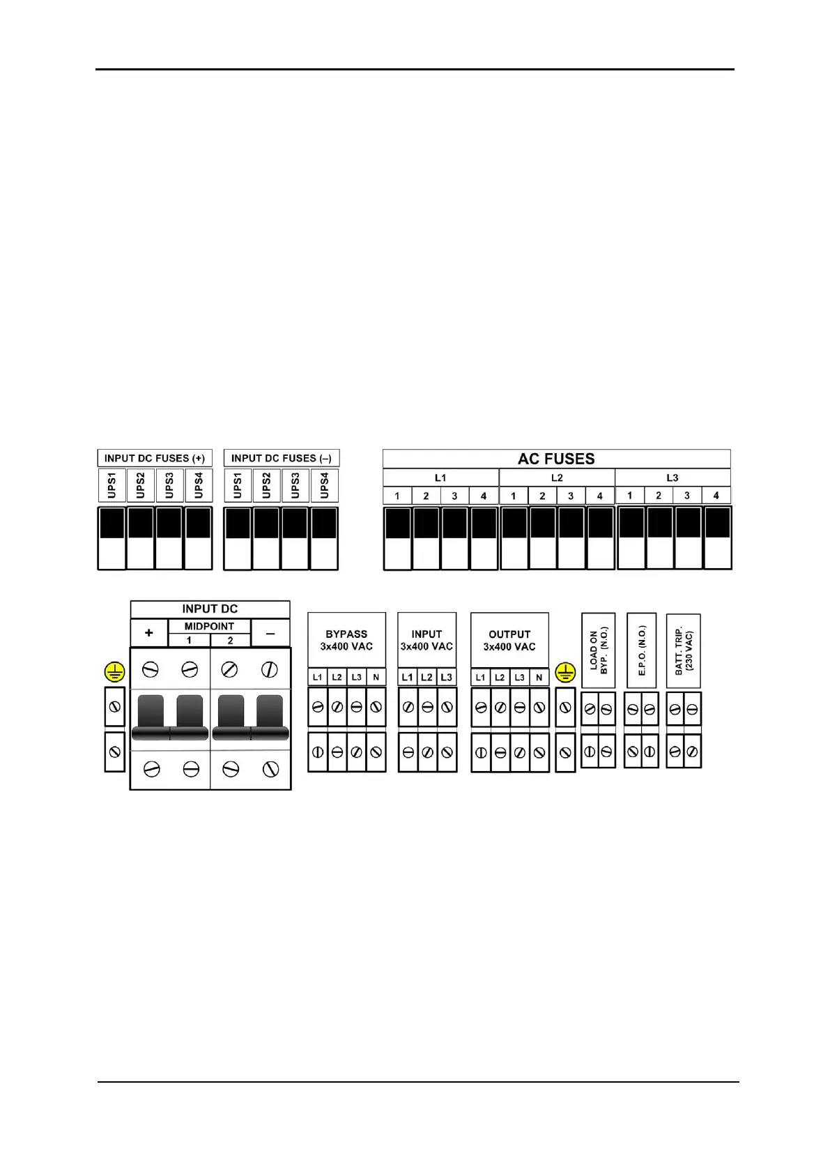
The following diagram illustrates the location and layout of the input and output power
terminals.
Figure 19: Power terminal locations on the rear panel
1. Connect the rectifier ac input, bypass ac input, and output cables.
2. Use a torque wrench to tighten the terminals to 270 lbs/in.
Note: Use copper conductors only.