GAMATRONIC ELECTRONIC INDUSTRIES LTD.
12
+
SA: 20, 30, and 40 kVA, Release 2.1
Figure 10: Ac power failure indication
3.7.3 Bypass operation (automatic)
During Bypass operation, the ac feeds the load via the bypass static switch. The red alarm
flashes to indicate an abnormal status.
LOAD LEVEL ---12:01:11---
L1: _____ 015A, 230V BATTERY: 868V
L2: _____ 012A, 230V UPS OK (ON)
L3: ______ 011A, 230V STSW OK (BYP)
Status
indications
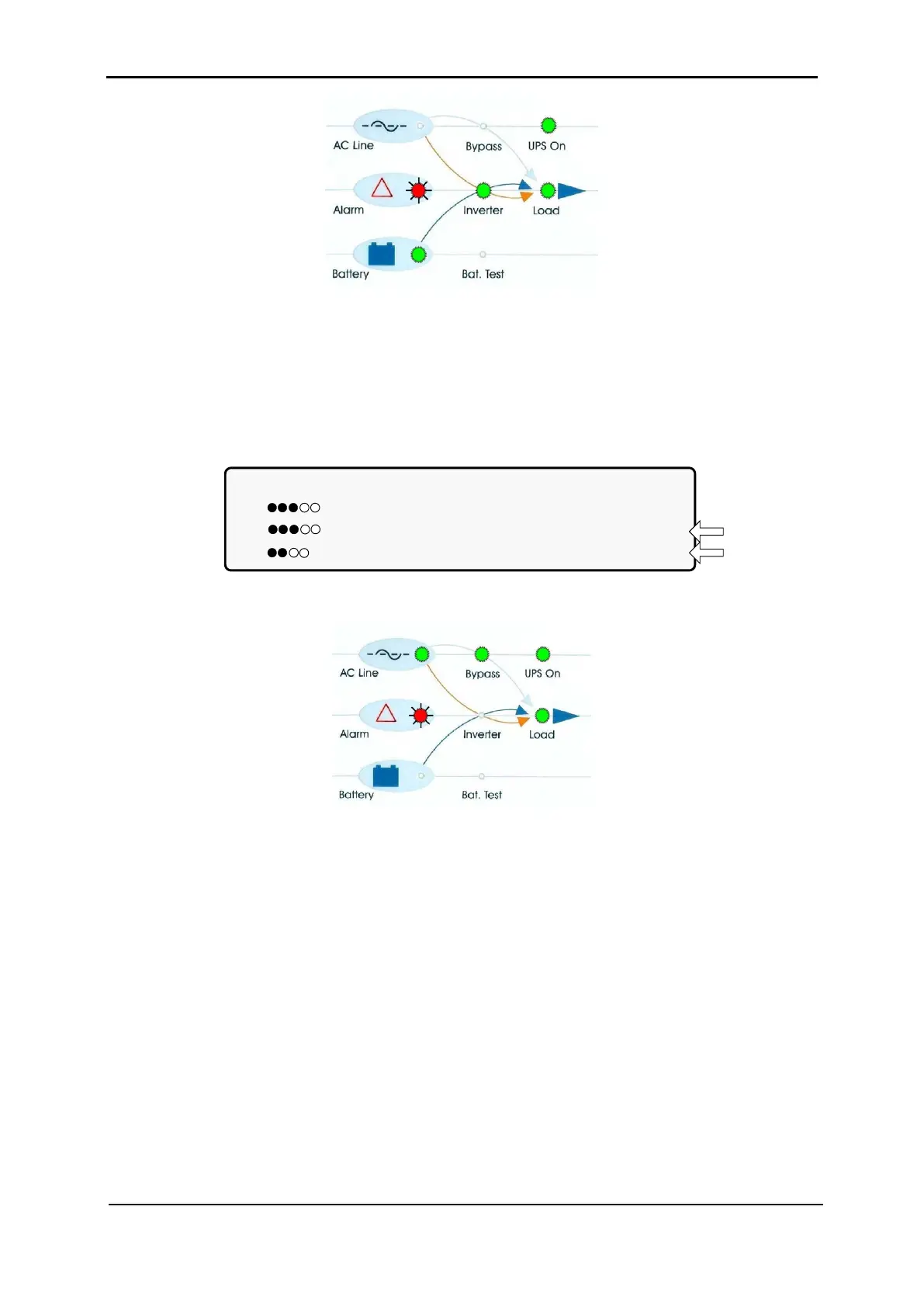
Figure 11: UPS in bypass mode
Figure 12: UPS in bypass mode
3.7.4 Bypass operation (manual)
If the Power+ SA is manually switched to bypass operation by pressing the Inv/Byp button,
the load is transferred to the mains ac input line. Transfer back to normal operation must be
performed manually. The red alarm indicator flashes to indicate an abnormal status (see
Figure 12).
3.7.5 Emergency power-off – EPO (manual)
An external Emergency Power Off (EPO) switch can be installed by the customer. The EPO
switch cuts power to the load in emergency situations. Once switched OFF by the EPO, the
POWER
+
must be restarted manually.
The EPO switch must be an N.O.-type, rated for at least 24 Vdc, 1 A.