GAMATRONIC ELECTRONIC INDUSTRIES LTD.
34
+
SA: 20, 30, and 40 kVA, Release 2.1
6.5 Special Terminal Connections
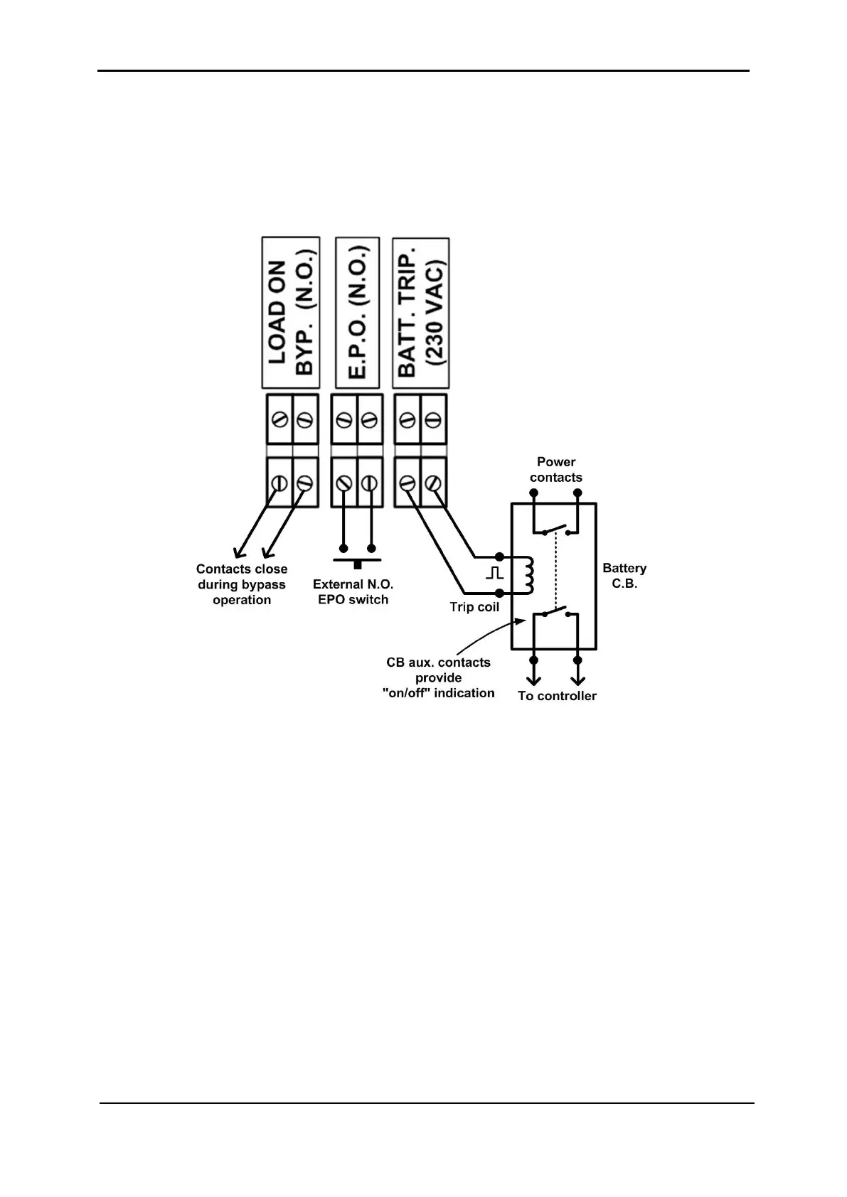
This section describes the special-purpose connections of the Power+ SA. Figure 27 shows
connections to the special terminals located on the rear of the Power+ SA, to the right of the
main ac and dc terminals.
Figure 27: Special purpose connections
6.5.1 Load on Bypass Alarm
This output dry contact is Normally Open, and closes when the UPS transfers the load to
bypass (Figure 27). The dry contact reopens again when the UPS returns to inverter mode.
6.5.2 Battery Trip Coil
The battery trip coil terminals are intended to be connected to the trip coil of the battery
circuit breaker (Figure 27). If this is done and the EPO switch is activated, the P
OWER+ SA
sends a pulse of 230 V to the battery circuit breaker trip coil, causing the battery circuit
breaker to turn OFF.
Use of the battery trip coil means that not only will use of the EPO switch cut all ac output
from the UPS, it will also turn off the battery circuit breaker.