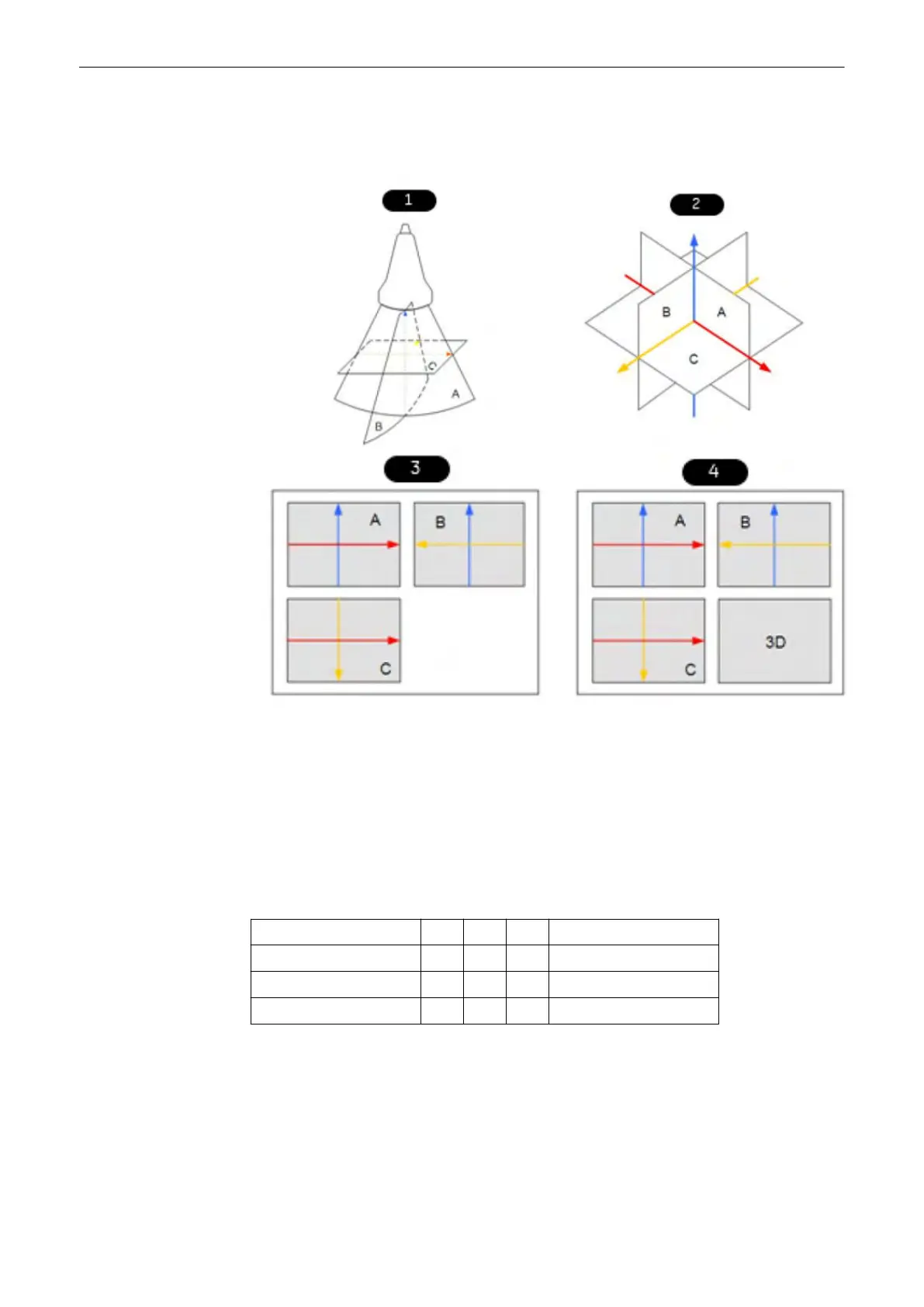
The standard representation: 3 sectional planes. The 3 orthogonal sectional planes are
simultaneously displayed on the screen. Each quarter of the monitor displays a sectional view
through the volume body as shown below.
Figure 8-1 Sectional planes
1. Scan situation (init. condition)
2. Sectional planes
3. Visualization Mode: Multiplanar
4. Visualization Mode: Render
The intersection lines of the planes are displayed in colors:
AB = blue AC = red BC = yellow
Orientation of intersection lines on the screen:
Section/field A B C
Intersection line AB V V P V = Vertical
Intersection line AC H P H H = Horizontal
Intersection line BC P H V P = Perpendicular
By this definition the relation of the position of the 3 images A, B, C is also indicated (as made
clear by the direction of arrows). The presentation of 3 orthogonal sectional planes may lead to
non-conformance with the conventional customized orientation to the patient in 2D-
sonography. An identification system - the automatic display of the direction of section - will
clarify.
Please note:
3D and 4D Mode
Voluson™ SWIFT / Voluson SWIFT+ Instructions For Use
5831612-100 R
evision 4 8-3
 Loading...


