c. Press down the upper arm and connect the upper ball pin to the
steering knuckle. Install and tighten the nut to the specified
torque.
Tightening force: 145
15N m
d. Install the new split pin.
Remarks: It should align the notch of nut with the pinhole when
install the split pin; the nut can be tightened but not
loosedduringthealignment.
e. Install and tighten the lower ball pin nut to specified torque.
Tightening force: 230
20N m
f. Install the new split pin.
Remarks: It should align the notch of nut with the pinhole when
install the split pin; the nut can be tightened but not
loosedduringthealignment.
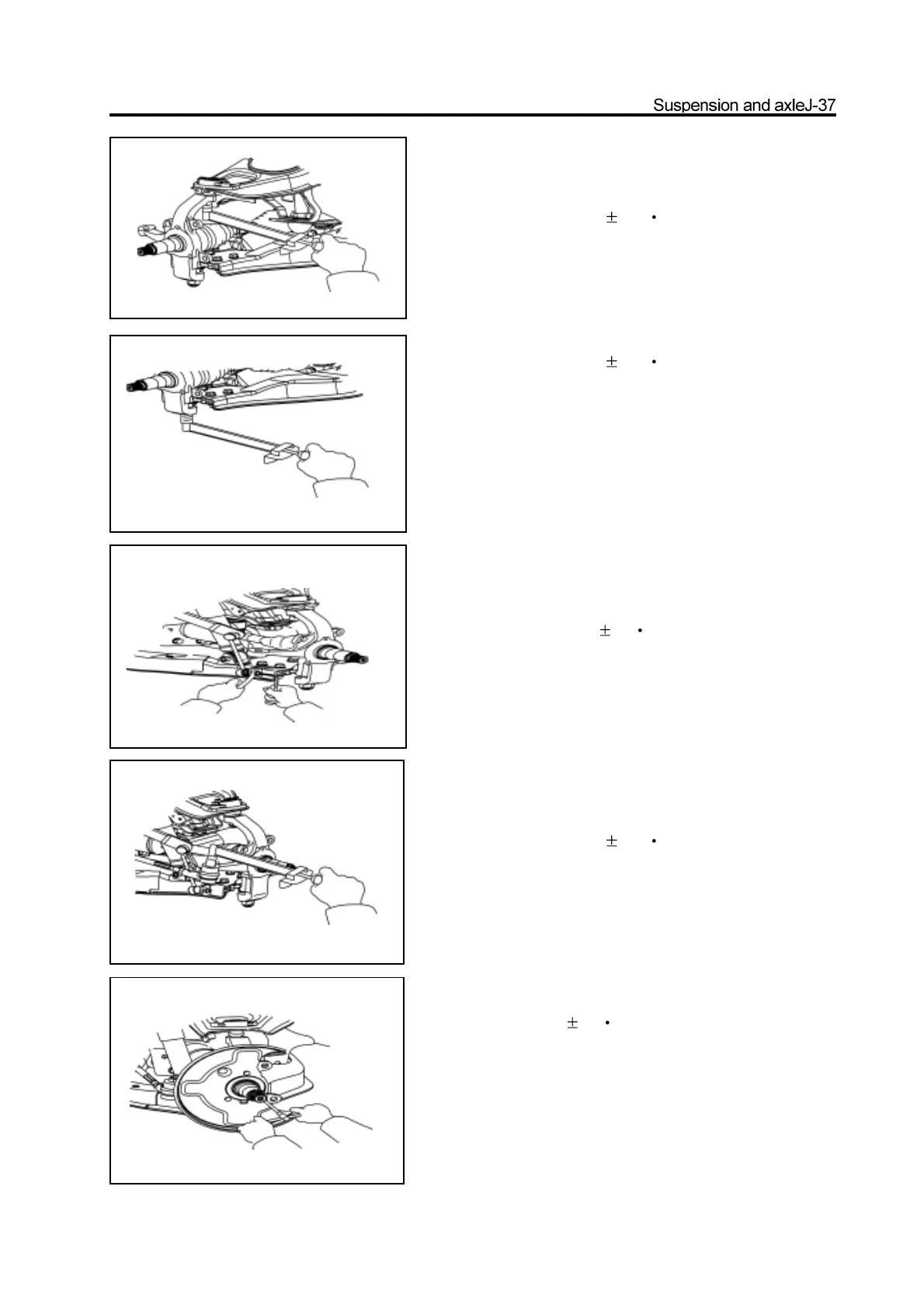
2. Connect the stabilizer bar to the lower arm
Support the lower arm by jack; use the inner hexagon spanner to fix
the ball pin and tighten the self-locking nut to specified torque.
Tightening force: 63 5N m
3. Connect the steering cross rod to the steering
knuckle arm
a. Tighten the slotted nut according to the specified torque.
Tightening force: 170 15N m
b. Install the new split pin.
Remarks: It should align the notch of nut with the pinhole when
install the split pin; the nut can be tightened but not
loosedduringthealignment.
4. Install the brake cover
Tightening force: 23 3N m
5. Install the front hub and disc brake
(Refer to section “Front Hub”)