1-2
z For the details of the interface modules, refer to H3C S5120-EI Series Ethernet Switches
Installation Manual.
z Among S5120-EI series switches, S5120-28C-EI, S5120-52C-EI, S5120-28C-PWR-EI, and
S5120-52C-PWR-EI switches support IRF stack.
You can connect physical stack ports of the S5120-EI series with either the CX4 dedicated cables or
fibers according to the interface type on the interface module. Dedicated cables provide higher
reliability and performance; whereas fibers connect physical devices located very far from each other
and provide flexible application.
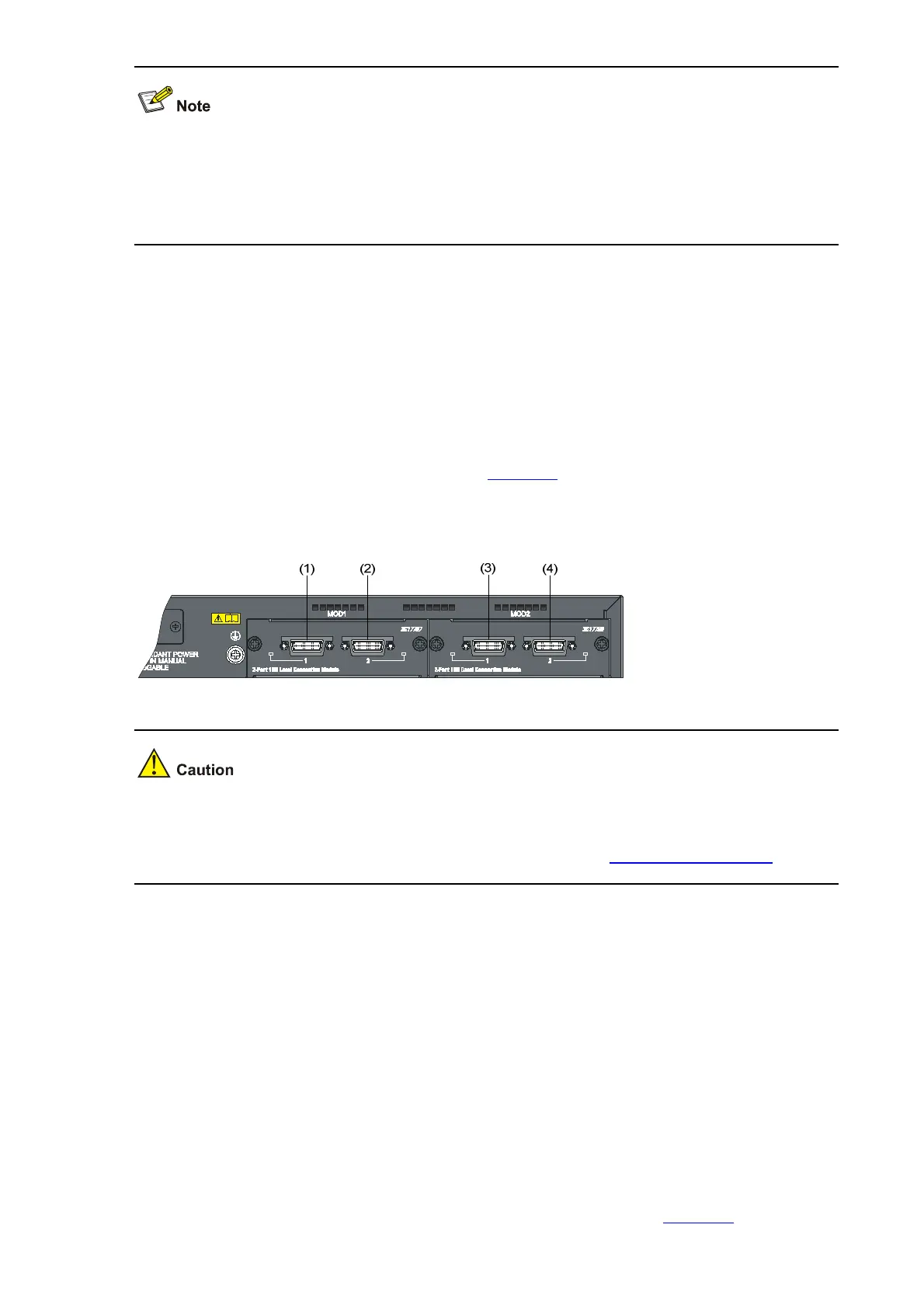
The physical stack ports are numbered according to their physical locations on the rear panel of the
S5120-EI series. With the rear panel facing you, the physical stack ports are numbered successively
from left to right: ports on the interface module in slot 1 are numbered 1 and 2, and ports on the interface
module in slot 2 are numbered 3 and 4, as shown in
Figure 1-1, which illustrates an example of inserting
a CX4 dual-port interface module.
Figure 1-1 Numbering physical stack ports
If you insert a one-port interface module into the slot, then the number of the physical stack port
corresponding to the module in slot 1 is 1, and the number of the physical stack port corresponding to
the module in slot 2 is 3. For the number of physical stack ports, see
Configuring Stack Ports.
Physical stack ports can be used for both stack connection and service data transmission. When
establishing a stack, you need to specify that the physical stack ports are used for the stack, that is, bind
them with logical stack port(s) to implement stack connection and establishment.
Logical stack port
You can set a physical stack port as a logical stack port, which is used to transfer data and protocol
packets among stack members. An S5120-EI series can be configured with two logical stack ports,
which are numbered 1 and 2, to connect other devices in a stack.
An IRF stack typically has a bus connection or a ring connection:
z Bus connection: Given a device, its logical stack port 1 is connected to logical stack port 2 of
another device, and its logical stack port 2 is connected to logical stack port 1 of a third one;
devices are connected to form a single straight connection, as shown in
Figure 1-2.

 Loading...


