153
_____________________________________________________________________________________________
9.1 External I/O Terminal
______________________________________________________________________________________________
H.V.ON
―――――――
READY
―――――――
TEST
――――――
Voltage Output
W-MODE
――――――――――
I-MODE
―――――――――
140 ms max.
STEP-END
――――――――――
(Program mode)
100 ms
H.V.ON
―――――――
READY
―――――――
TEST
――――――
Voltage Output
W-MODE
――――――――――
I-MODE
―――――――――
210 ms max.
STEP-END
――――――――――
(Program mode)
100 ms
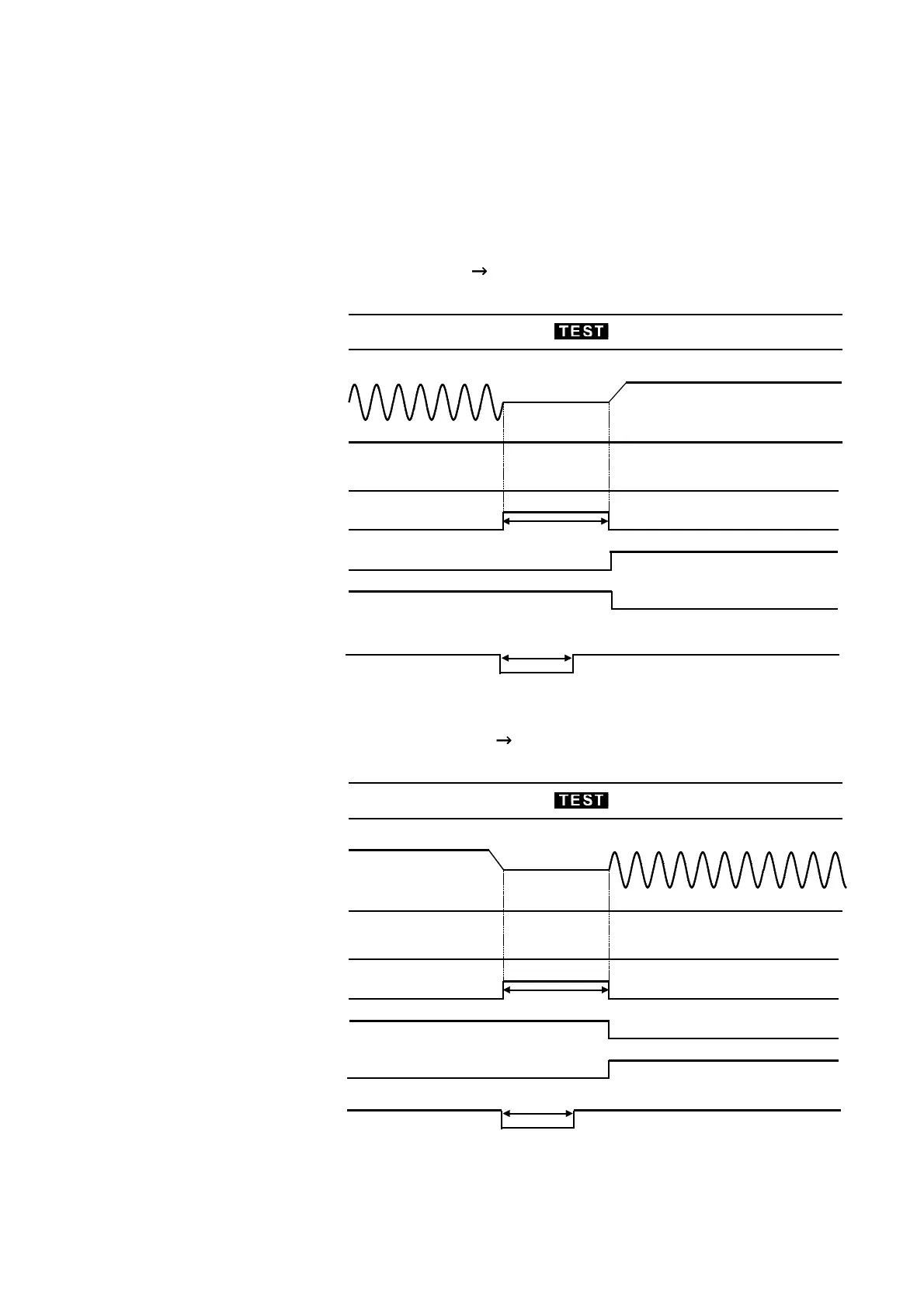
(4) Auto-test-mode and program-mode switching timing chart
This figure shows the switching timing chart of the unit when it is in the
auto-test mode. In this mode, withstand-voltage and insulation-resistance
tests are conducted successively. The unit switches to the next test when the
output-voltage value has dropped sufficiently. The
TEST
―――――――
signal remains at
LOW level until a series of tests is completed. In the program mode, each
time a test is completed, the
STEP-END
―――――――――――――
signal enters LOW level.
Withstand-voltage test Insulation-resistance test
Insulation-resistance test Withstand-voltage test