206
_____________________________________________________________________________________________
10.6 GP-IB Command Transfer Methods
______________________________________________________________________________________________
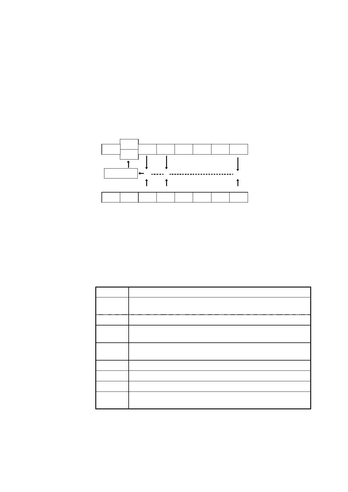
MSS
RQS
ESB MAV
Logical sum
ESB MAVUnused
×
UnusedUnusedUnused ESB0
UnusedUnusedUnused ESB0Unused
Status byte register (STB)
Service request enable register (SRER)
bit 3 bit 2 bit 1 bit 0bit 5 bit 4bit 7 bit 6
bit 7
bit 6
bit 5 bit 4 bit 3 bit 2 bit 1 bit 0
Bit 7 Unused.
Bit 6
RQS
Set to 1 when a service request is issued.
MSS Logical sum of the other bits of the status byte register
Bit 5
ESB
Standard event summary (logical sum) bit
Shows a logical sum of the standard event status register.
Bit 4
MAV
Message available.
Shows that there is at least one message in the output queue.
Bit 3 Unused.
Bit 2 Unused.
Bit 1 Unused.
Bit 0 Eventsummarybit0
Shows a logical sum of event status register 0.
Status Byte Register
(1) Status byte register (STB)
The status byte register is an 8-bit register whose contents are output from
the 3153 to the controller, when serial polling is being performed.
If any bit in the status byte register has changed from 0 to 1 (provided that it
is a bit which has been set in the service request enable register as a bit
which can be used), then the MSS bit is set to 1. Simultaneously with this
the RQS bit is also set to 1, and a service request is generated.
The RQS bit is synchronized with service requests, and is read out and
simultaneously cleared when serial polling is being performed. Although the
MSS bit is only read out on an ∗
STB?
query, on a ∗
CLS
command for
example it is not cleared until the event is cleared.
Status byte register bit assignments
(2) Service request enable resister (SRER)
This register masks the status byte register. Setting a bit of this register to 1
enables the corresponding bit of the status byte register to be used.