Input 1 is typically the PV of some upper controller and Input 2 is
typically that controller's output. If the upper control fails, the upper
device or some watchdog opens the digital input switch and
UDC2800 back-up PID A control is active.
When the upper control reactivates, the digital input switch is closed
and the Auto/Manual Station becomes a repeater station and allows
the upper control output signal to pass through.
Configuration
There are some things to consider when configuring the controller.
The PV range stays as the Input 1 range, even while Input 2 is the PV
when the switch is closed; therefore:
n
The Input 2 High Value must be less than or equal to the Input 1
High Value.
(Suggest: Input 2 High Value = 100.0)
n
The Input 2 Low Value must be greater than or equal to the Input
1 Low Value.
(Suggest: Input 2 Low Value = 0.0)
n
The Tuning Gain 2 must be equal to (Input 1 High Value - Input 1
Low Value) / (Input 2 High Value - Input 2 Low Value).
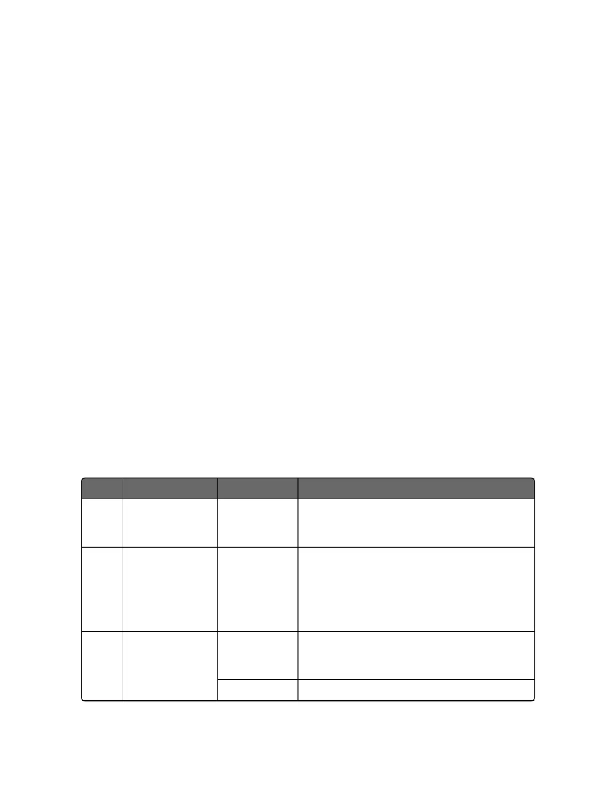
See the following table for the configuration procedure.
Table 5-16: Auto/Manual Station Mode Configuration Procedure
Step Operation Press Result
1 Select
Algorithms
set up group
Setup key Until you see Algorithms set up group.
2 Select Control
Algorithm
Function key Enter in the first function prompt of the
Algorithms set up group: Control Algorithm.
Press the Function key again to enter in the
first configuration prompt of Control
Algorithm.
3 Select
PD+Manual
Reset function
Increment key
or Decrement
key
Until you see the selection PD+Manual Reset.
Function key Select the selection PD+Manual Reset.
203
Chapter 5 - Monitoring and Operating the Controller

 Loading...


