WinMax Lathe Conversational Part Programming v546CO Conversational Part Programming 2-77
When Linear is selected in the COORDINATES field, these fields appear:
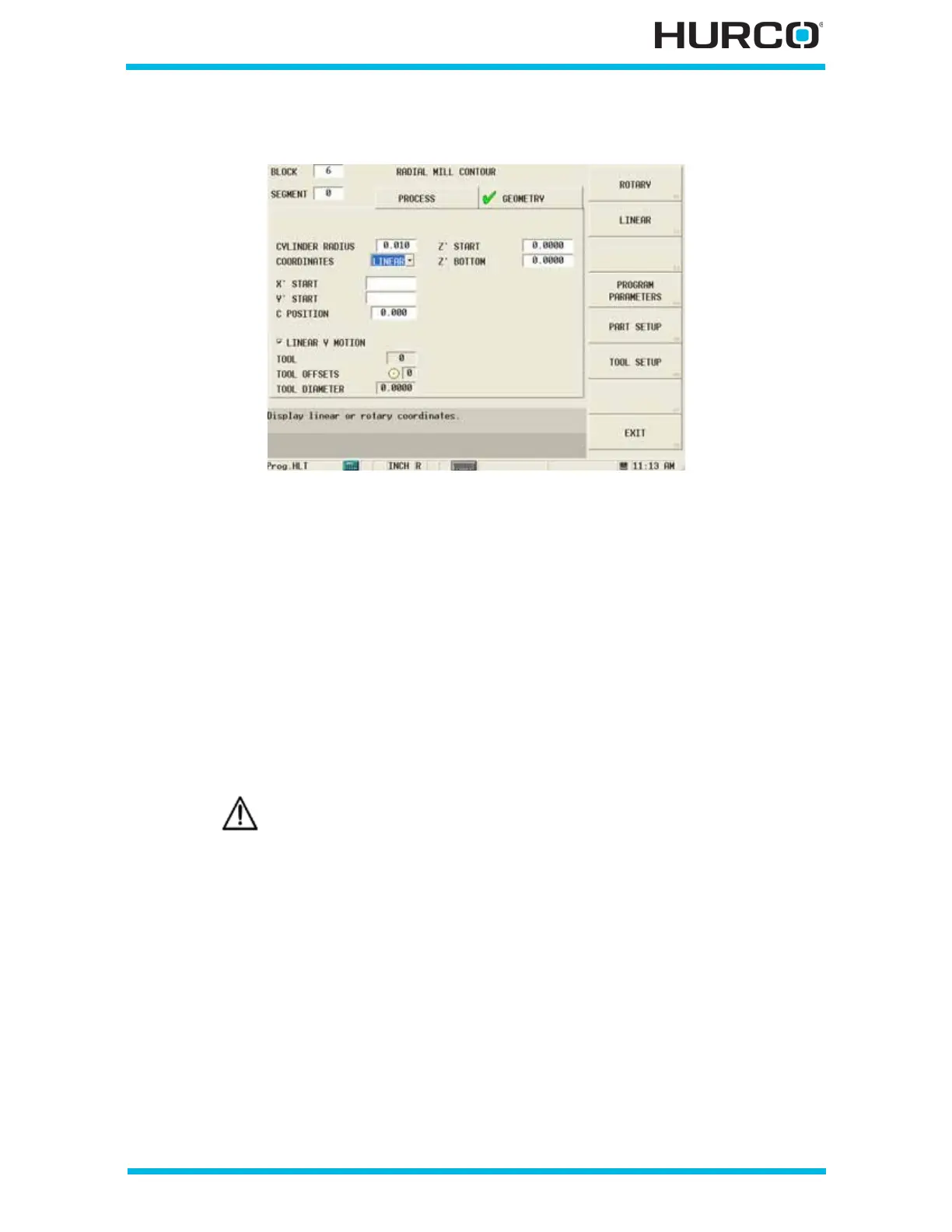
Figure 2–65. Live-Tooling Radial Mill Contour screen Geometry tab: Linear Coordinates
• X’ START—defines the X Startpoint for the first segment of the contour. The
X’ axis will move in the physical Z direction.
• Y’ START—defines the Y Startpoint for the first segment of the contour. The
Y’ axis will be wrapped on the cylinder diameter.
• C POSITION—defines the angle to position the C axis for the first segment
of the contour. This field appears when the Linear Y Motion checkbox is
selected. This field is available with TMX MY and TMX MYS series machines.
• LINEAR Y MOTION—select this checkbox to cause Y-Axis Motion using the X
and X’ axes. When this checkbox is clear, Y-Axis Motion occurs using the X
and C axes. Please refer to Programming Coordinates and Linear Y Motion, on
page 2 - 68 for examples. This field is available with TMX MY and TMX MYS
series machines.
• Z’ START—defines the location where Plunge Feedrate begins. The feedrate
is set in the Plunge Feed field in the Process tab. The Z’ axis will move in the
physical X direction.
• Z’ BOTTOM—defines the bottom of the hole and the location where the
Plunge Feedrate ends. The Z’ axis will move in the physical X direction. These
fields are read-only and are carried over from Tool Setup for the tool specified
in the Process tab.
• TOOL—identifies the tool number that will be used in the part program.
• TOOL OFFSETS—identifies the tool offset and orientation programmed in
Tool Setup that will be used. The tool offset defaults to the same number as
the tool.
• TOOL DIAMETER—contains the tool diameter programmed in Tool Setup for
the current tool. This field is read-only and can only be edited in Tool Setup.
Linear Y-Axis Motion is limited. The amount of Y travel is affected by
the X position and by any X-Axis tool length offset.
 Loading...


