2 - 70 Conversational Part Programming v546CO WinMax Lathe Conversational Part Programming
Linear Y Motion
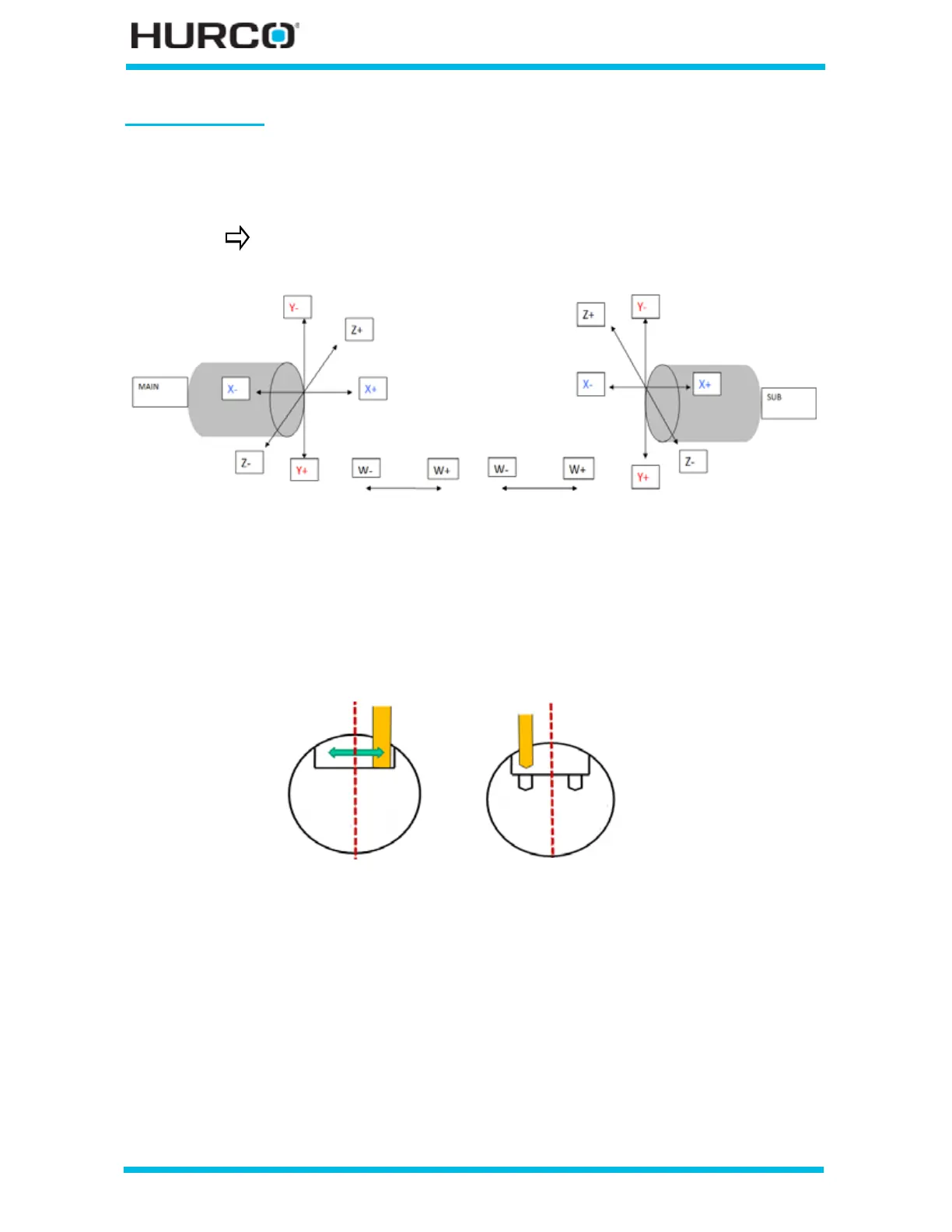
The following figure shows the Y-Axis coordinate system mapping for TMX MY and TMX
MYS machines. When Linear Y Motion is selected on the Geometry tab, linear Y-axis
motion occurs.
Figure 2–59. Main and Sub-spindle Radial surface of the part with Linear Y
With Linear Y selected, TMX MY and TMX MYS machines can perform Linear Milling to
create flat bottoms and right-angle walls for milled features and to machine holes parallel
to the Y axis.
Figure 2–60. Radial Cutting—Y-Axis motion
Please refer to Radial Lines and Arcs, on page 2 - 71, Radial Circle, on page 2 - 89, Radial
Frame, on page 2 - 95, Radial Slot, on page 2 - 102, or Radial Lettering, on page 2 - 110
for information about the Geometry tab screen for the different types of Radial Milling.
For information about Radial Holes, please refer to Radial Holes, on page 2 - 114.
TMM machines do not use this mapping.
Main Spindle Linear Y selected
Part Coordinate system
Sub-spindle Linear Y selected
Part Coordinate system
Milling
Drilling
 Loading...


