2 - 76 Conversational Part Programming v546CO WinMax Lathe Conversational Part Programming
Geometry Tab
The Radial Mill Contour screen appears with Process and Geometry tabs. Program the tool
and cutting information using the Process tab. Describe the finish shape using the
Geometry tab.
Finishing follows the geometry of the contour defined in the Geometry tab. The fields on
the Geometry tab are defined as follows:
• CYLINDER DIAMETER or RADIUS—defines the diameter or radius of the
cylinder.
• COORDINATES—defines the coordinates as either Linear or Rotary.
• Linear coordinates are used when working from a flat drawing. When
Linear is selected, the X coordinates move in the physical Z direction, the
Y coordinates wrap around the C axis, and the Z coordinates move in the
physical X direction.
• Rotary coordinates move around the cylinder as specified.
The fields are based on your selection in the Coordinates field (Rotary or Linear).
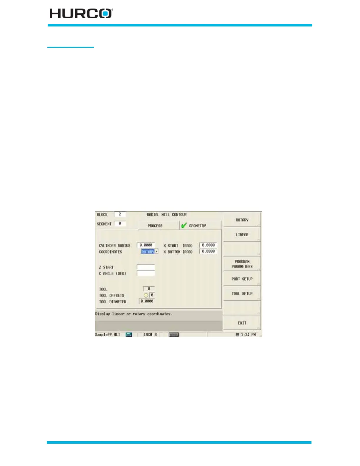
When Rotary is selected in the COORDINATES field, these fields appear:
Figure 2–64. Live-Tooling Radial Mill Contour screen Geometry tab: Rotary Coordinates
• Z START—defines the location where Plunge Feedrate begins. The feedrate is
set in the Plunge Feed field in the Process tab.
• C ANGLE (DEG)—defines the angle of the line segment from the start point
to the end point, measured counterclockwise from the home position.
• X START (DIA) or (RAD)—defines the location where Plunge Feedrate
begins. The feedrate is set in the Plunge Feed field in the Process tab.
• X BOTTOM (DIA) or (RAD)—defines the bottom of the hole and the
location where the Plunge Feed Rate ends.
 Loading...


