WinMax Lathe Conversational Part Programming v546CO Conversational Part Programming 2-153
These fields are read-only and are carried over from Tool Setup for the tool specified in
the Process tab.
• TOOL—identifies the tool number that will be used in the part program.
• TOOL OFFSETS—identifies the tool offset and orientation programmed in
Tool Setup that will be used. The tool offset defaults to the same number as
the tool.
• TOOL DIAMETER—contains the tool diameter programmed in Tool Setup for
the current tool. This field is read-only and can only be edited in Tool Setup.
Axial Frame
From the New Block (Axial Milling) screen select Axial Frame F3, and the Axial Mill Frame
screen appears with Process and Geometry tabs. Program the tool and cutting
information using the Process tab. Describe the finish shape using the Geometry tab.
Process Tab
The program determines how many rough passes to make to remove the material based
on the entries in the Process tab fields.
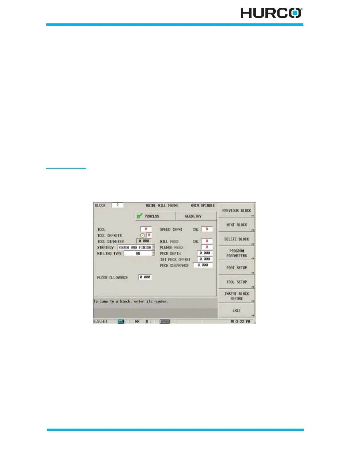
Figure 2–126. Live-Tooling Axial Mill Frame screen Process tab
The Process tab fields are defined as follows:
• TOOL—identifies the tool number that will be used in the part program.
• TOOL OFFSETS—identifies the tool offset and orientation programmed in
Tool Setup that will be used. The tool offset defaults to the same number as
the tool.
• TOOL DIAMETER—contains the tool diameter programmed in Tool Setup for
the current tool. This field is read-only and can only be edited in Tool Setup.
 Loading...


