2 - 158 Conversational Part Programming v546CO WinMax Lathe Conversational Part Programming
Geometry Tab
Finishing follows the geometry of the contour defined in the Geometry tab.
Finishing follows the geometry of the contour defined in the Geometry tab. The fields on
the Geometry tab are defined as follows:
• COORDINATES—defines the coordinates as either Rectangular or Polar.
• Rectangular coordinates are used when working from a flat drawing.
• Polar coordinates move around the cylinder as specified.
The remaining fields are based on your selection in the Coordinates field (Polar or
Rectangular).
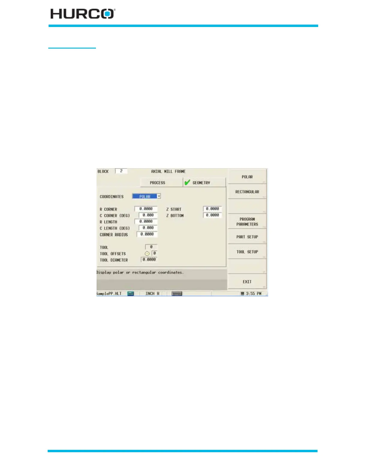
When Polar is selected in the COORDINATES field, these fields appear:
Figure 2–130. Live-Tooling Axial Mill Frame screen Geometry tab: Polar Coordinates
• R CORNER—defines the starting distance from the centerline.
• C CORNER (DEG)—defines the angle of the circle from the start point to the
end point, measured counterclockwise from the home position.
• R LENGTH—defines the starting distance from the centerline.
• C LENGTH (DEG)—defines the length of the frame, in degrees, along the C
axis, measured counterclockwise from the home position.
• CORNER RADIUS—defines the radius of all four corners of the frame, which
becomes the reference corner.
• Z START—defines the location where Plunge Feedrate begins. The feedrate is
set in the Plunge Feed field in the Process tab.
• Z BOTTOM—defines the bottom of the hole and the location where the
Plunge Feed Rate ends.
 Loading...


