2 - 36 Conversational Part Programming v546CO WinMax Lathe Conversational Part Programming
Chamfer Element
A Chamfer operation creates a straight line that joins two other elements and is tangent
to both.
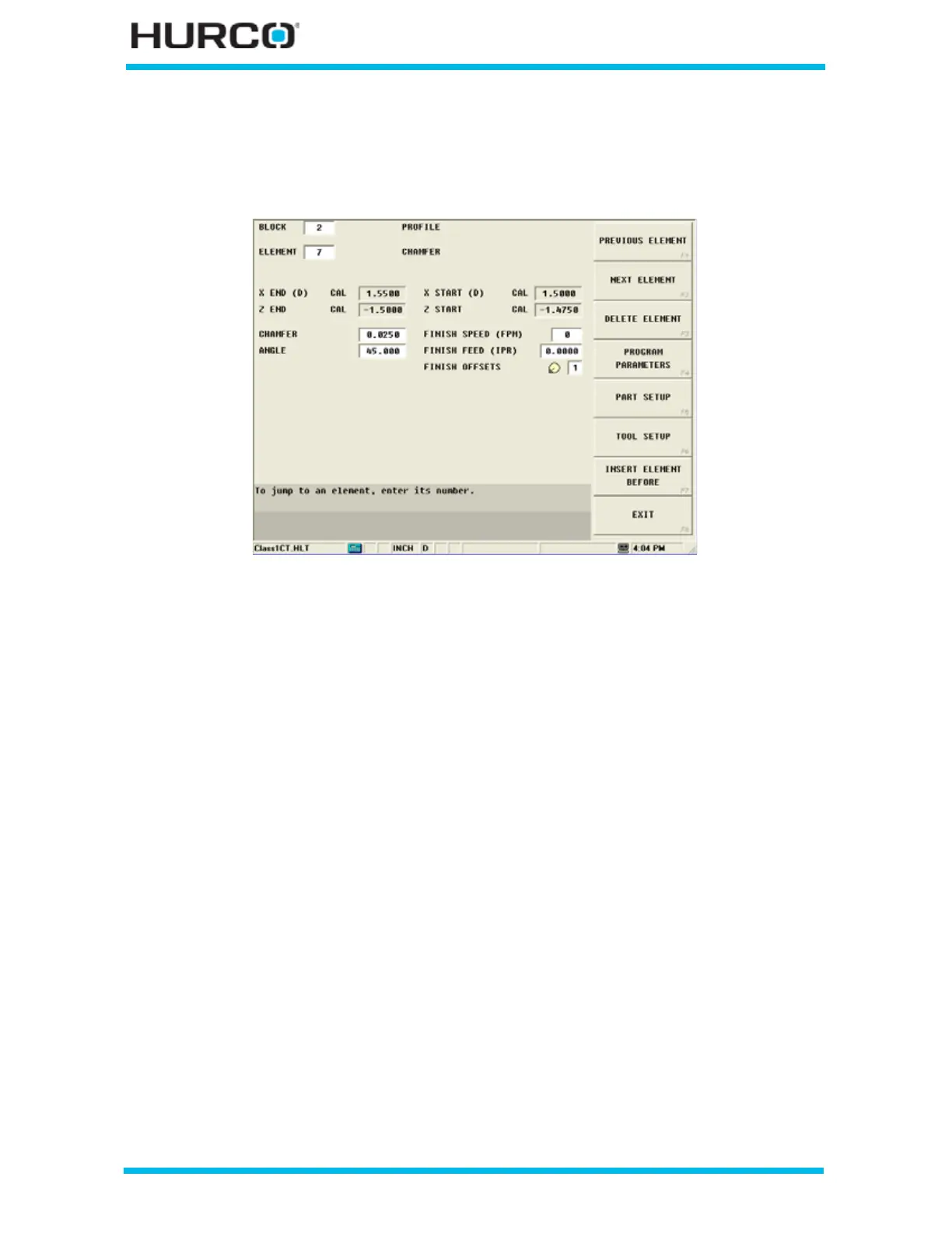
Figure 2–23. Chamfer Element screen
A chamfer can be used to join these types of elements:
• two Face elements.
• a Face element and a Turn element.
The elements to be joined must have a theoretical point of intersection.
Here are some guidelines that must be followed when creating a chamfer:
• The first or last element of a Profile data block cannot be chamfer elements.
• Chamfer elements can only be adjacent to turn and face elements.
• Blend arc or chamfer elements cannot be adjacent to one another in a
program. For example, if Element 2 is a blend arc, neither Element 1 nor 3
can be blend arc elements.
• Elements that are adjacent to the chamfer element must intersect at some
point in their theoretical plane. Therefore, if Element 2 is a chamfer, Elements
1 and 3 must theoretically intersect at some projected point.
• The length of a chamfer element cannot be too large and intersect the two
adjoining elements.
• If any coordinate (start point, center point, or end point) is important to the
construction of the two elements to be chamfered, the element must be
programmed as a taper and not as a chamfer.
 Loading...


