WinMax Lathe Conversational Part Programming v546CO Conversational Part Programming 2-121
Radial Locations
From the New Radial Holes Operation screen select Radial Locations Cycle F2. The Radial
Holes Locations screen appears. The fields are defined as follows:
• CYLINDER DIAMETER or RADIUS—defines the diameter or radius of the
cylinder.
• COORDINATES—defines the coordinates as either Linear or Rotary, relative
to the part.
• Linear coordinates are used when working from a flat drawing. When
Linear is selected, the X coordinates move in the physical Z direction, the
Y coordinates wrap around the C axis, and the Z coordinates move in the
physical X direction.
• Rotary coordinates move around the cylinder as specified.
• Location Number—identifies the sequential number for the location. When
the fields for each location are filled in, press Enter. The next row fields
becomes active and the Location Number field increments by one.
When the cursor is in one of the Location fields (Z, C (DEG), X’, Y’, or Retract) these
softkey choices are available:
• DELETE LOCATION F4—delete a selected row of location fields.
• ADD LOCATION F5—add a row of location fields to the bottom of the list.
• INSERT LOCATION BEFORE F7—insert a row of location fields above the
selected row.
The remaining fields are based on your selection in the Coordinates field (Rotary or
Linear).
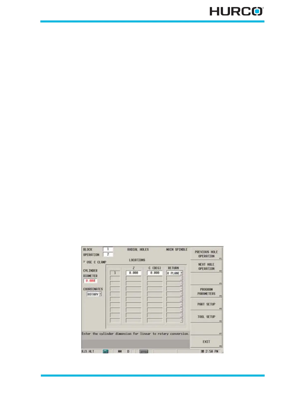
When Rotary is selected in the COORDINATES field, these fields appear:
Figure 2–101. Live-Tooling Radial Locations screen: Rotary Coordinates
 Loading...


