2 - 34 Conversational Part Programming v546CO WinMax Lathe Conversational Part Programming
Blend Arc Element
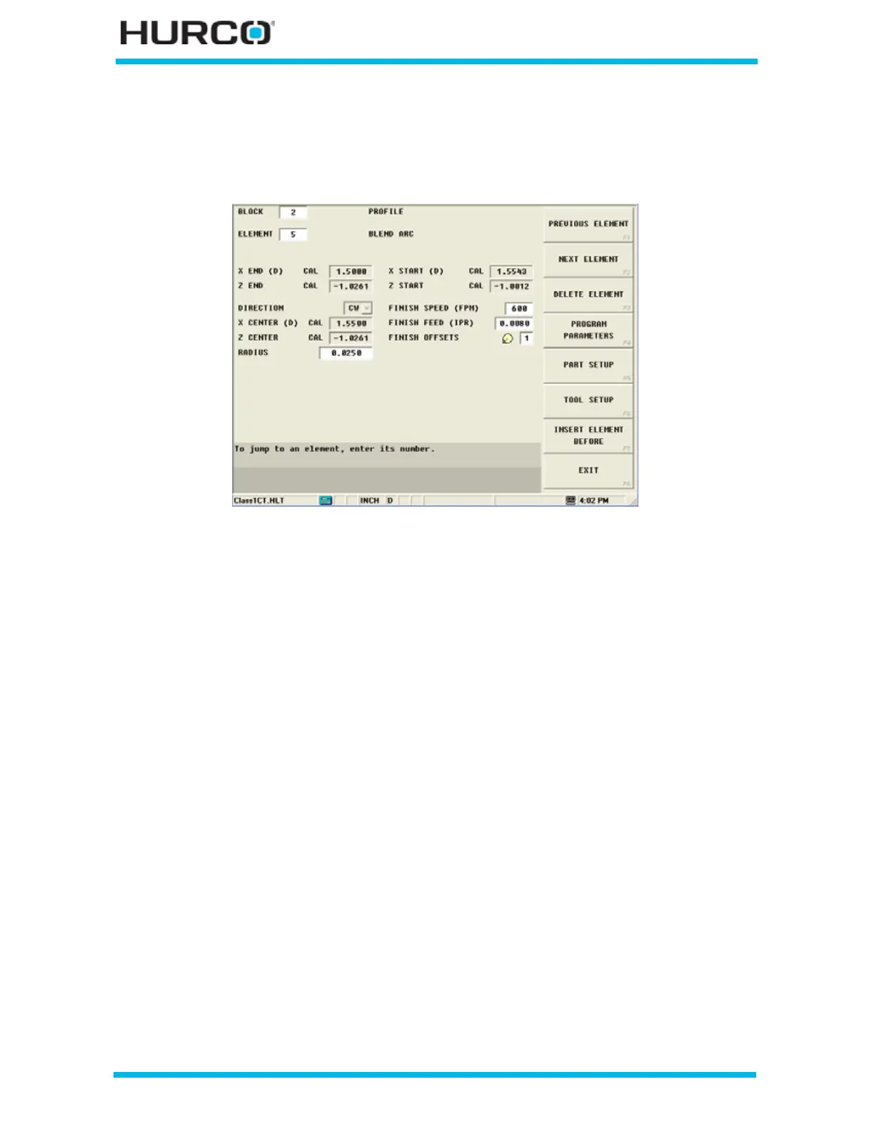
A Blend Arc operation creates a curved line that joins two other elements and is tangent
to both.
Figure 2–22. Blend Arc Element screen
A blend arc can be used to join these types of elements:
• two Face elements.
• a Face element and a Turn element.
• two Arc elements.
• a Taper to another element.
The elements to be joined must have a theoretical point of intersection. If the only
information known about an arc is its radius, it is easier to program it as a blend arc, if
the elements intersect.
Here are some guidelines that must be followed when creating a blend arc:
• The first or last element of a Profile data block cannot be blend arc element.
• Blend arc or chamfer elements cannot be adjacent to one another in a
program. For example, if Element 2 is a blend arc, neither Element 1 nor 3
can be blend arc elements.
• Elements that are adjacent to the blend arc element must intersect at some
point in their theoretical plane. Therefore, if Element 2 is a blend arc,
Elements 1 and 3 must theoretically intersect at some projected point.
• The radius of a blend arc element cannot be too large to be tangent to both of
the adjoining elements
• If any coordinate (start point, center point, or end point) is important to the
construction of the two elements to be blended, the element must be
programmed as an arc and not as a blend arc.
 Loading...


