WinMax Lathe Conversational Part Programming v546CO Sample Part Program 3-37
Step 20: Use Verification Graphics to view drawing of part for Blocks #1 and #2.
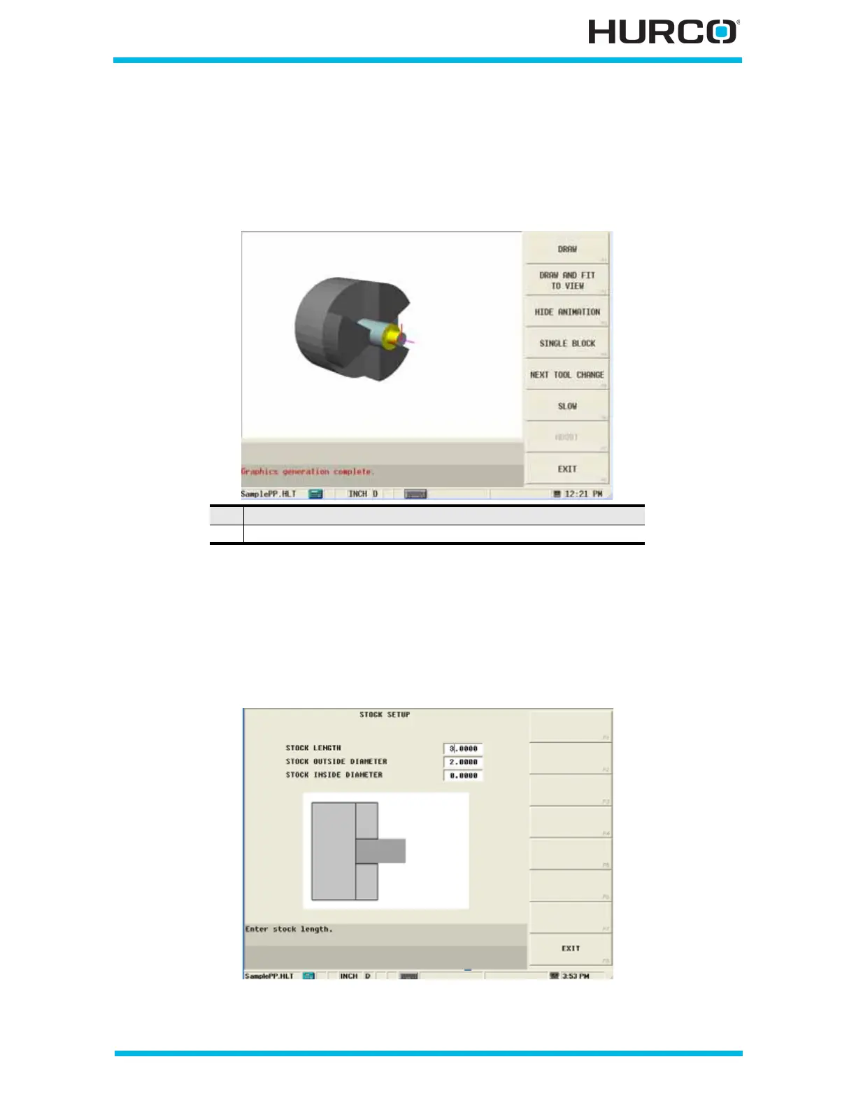
Select the Verify console key to view the tool path and stock with Verification Graphics.
The following 3-D figure shows the tool path and stock after being cut using the data from
Blocks 1 and 2:
Figure 3–54. 3-D Verification Graphics Sample Program Blocks 1 and 2
Step 21: Use Graphics to check stock length.
Notice in the graphic above that the stock is not as long as the part needs to be. To
correct this, from the graphics screen, select the SETUP F7 softkey followed by the STOCK
SETUP F1 softkey, shown on the sample screen above. The Stock Setup screen appears.
Figure 3–55. Stock Setup Screen
1 The vertical red line represents Part Zero
2 The horizontal pink line represents the stock centerline.
 Loading...


