WinMax Lathe Conversational Part Programming v546CO Conversational Part Programming 2-185
Axial Bolt Circle
From the Axial Holes screen, with the cursor in the Operation field, either select NEXT
HOLE OPERATION F2 or INSERT HOLE OPERATION F7. From the New Axial Holes
Operation screen select Axial Bolt Circle F3. The Axial Holes Bolt Circle screen appears.
The fields are based on your choice in the Coordinates field (Polar or Rectangular).
The fields on the Axial Bolt Circle screen are defined as follows:
• COORDINATES—defines the coordinates as either Linear or Rotary.
• Rectangular coordinates are used when working from a flat drawing.
• Polar coordinates move around the cylinder as specified.
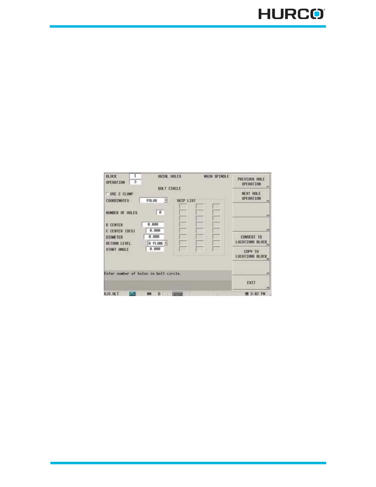
When Polar is selected in the COORDINATES field, these fields appear:
Figure 2–153. Live-Tooling Axial Bolt Circle screen: Polar Coordinates
• USE C CLAMP checkbox—engages the C Axis Clamp during the Hole
operation when this checkbox is selected.
• NUMBER OF HOLES—defines the number of holes for the bolt circle.
• R CENTER—defines the starting distance from the centerline. The default is
0.
• C CENTER (DEG)—defines the center of the bolt circle, measured
counterclockwise from the home position. The default is 0.
• RADIUS—defines the radius of the bolt circle.
• RETURN—identifies the level to which the tool should retract at the end of
the drill cycle. R Plane is the default.
• I PLANE—returns to the coordinate specified in the X/Z Start field.
• R PLANE—returns to the coordinate specified in the R Plane field.
• START ANGLE—defines the angle to the first hole, measured
counterclockwise from the home position.
 Loading...


